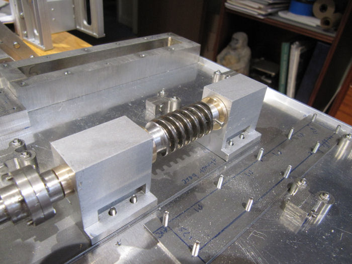
This afternoon I shaped a piece of the Acme threaded rod to make the worm gear. The screws will locate it on flat spots on the rod, they need to be shortened.
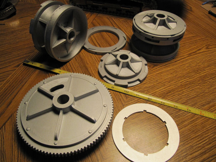
For those who may be wondering why I 3D printed some of the rope and chain drum parts, this may help explain my thoughts. Here are the pieces for just the chain drums, one set assembled, one set aprt on the table, plus the worm wheel with its printed side panels. They would have required about 18" of 6" bar to make from scratch, not even counting the rope drums shown previously. Also, the shapes needed would have been very hard to do without CNC, especially around the chain path on the drum in the upper left corner of the picture. There will be a number of metal parts added to these to make the ratchets and brake bands. The main drums spin freely on the shaft, while the worm wheel and the flanged plates, like the one just above the '9' on the tape measure, are fixed to the shaft. A set of ratchets will sit inside the slots in that plate, with the open ring in the upper center pushing one end of the ratchets up into recesses in the chain drums to make them move. An interesting arrangement, allowing the chain drum to freewheel when desired, with speed slowed as needed by a brake band around one end. The plans showed all the pieces needed, but it was finding a patent about the mechanism that taught me how it all comes together.
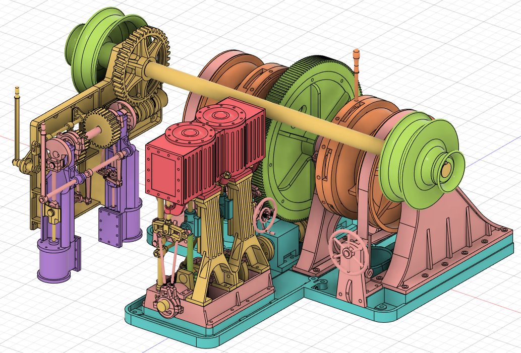
So, next up will be the three upright brackets that sit on bases already on the deck plate, and hold up the main shaft of the chain drum assembly. Going to take some plotting and planning to work out how to make those brackets. Two of those brackets are visible in this CAD view, in pink on the right hand end, either side of the orange chain drum with the handle sticking out the top (which controls the ratchet engagement). The third one is over on the left end but obscured by all the other parts. The brackets have a lot of curves and flanges around the edges, I need to decide what to mill out and what gets bolted/soldered on.


 Recent Posts


 Sort of glad the papers didn't include a picture of him...