William Ripper in his 1914 book
Machine Drawing & Design has a helpful image to show the relationship between the pitch circle and the generating circle of a cycloid gear.
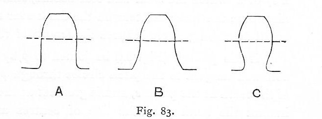
Tooth A has a generating circle with the diameter equal to the radius of the pitch circle, this gives a straight line for the dedendum flank.
Tooth B has a generating circle that has a diameter less then the radius of the pitch circle, this has the dedendum curves make the root of the gear thicker.
Tooth C has a generating circle that has a diameter larger than the pitch circle radius, this causes undercutting at the root and should never be used.
I looked at all the Lima Shay drawings in my collection and the ones that had tooth forms shown there was a mix of A and B tooth forms.
I wish Woodbury had given the
American Machinist issue information for the image of the Dengg machine, as he did for several other machines..... That research will have to wait.
The link that has the process of generating cycloid gears had a good overview of the pros and cons of cycloid gears.
https://www.tec-science.com/mechanical-power-transmission/cycloidal-gear/geometry-of-cycloidal-gears/"Pros and cons of cycloidal gears
The cycloidal shape of a tooth leads to less wear of the tooth flanks during meshing and thus to lower friction losses in comparison to the involute shape. The reason for this is the lower contact pressure (lower hertzian contact stress), since a convex and a concave flank always meet in mesh and nestle up against each other, so to speak."
"Furthermore, cycloidal gears can be produced with a significantly lower number of teeth without undercutting compared to involute gears. In this way, gears with only three or even two teeth can theoretically be produced."
"The lower friction and the low number of minimum teeth are the main reasons why cycloidal gears are/were often found in clocks."
"Despite the mentioned advantages of cycloidal gears, involute gears are still the most commonly used type of gears in mechanical engineering! The reason is the relatively simple production of an involute shape (straight tool flanks) compared to a cycloidal shape (curved tool flanks)."
"Furthermore, cycloidal gears are very sensitive to an inaccurate adjustment of the centre distance, which then leads to a change in the transmission ratio. For these reasons, cycloidal gears are hardly found in mechanical engineering but are only used in special cases such as in the watch industry, for roots type blowers or for the drive of gear racks."
The first sentence of the last parragraph is the reason that cycloid gears are a bad idea with a Shay locomotives. Almost all of the Shay trucks were equalized or had springs on the left side. This will cause pitch errors on the bevel gears as the left side moves up and down. The curve changes at the pitch line so this makes the wrong curves run together, add some grease and dirt and this will lead to gear wear. So yes there is an engineering reason why the tales of gears wearing out are true. At some point Lima switched to involute gears and I have seen a 1922 Lima ad stating that the gears now had a two year guarantee.
Cheers Dan


