Author Topic: Shay gears (parallel depth bevel gears graphical tutorial)  (Read 8156 times)

Offline Dan Rowe

  • Full Member
  • ****
  • Posts: 1170
  • Dripping Springs TX USA
Shay gears (parallel depth bevel gears graphical tutorial)
« on: September 07, 2020, 08:11:10 PM »
Years of searching has never led to finding a sutiable bevel gear set for a 7/8" Shay. The face length is always to short and to make matters worse I can not even find a good compromise. The stock gears always stick out one end or the other not in the middle of a proper Shay gear.

I know at least three ways to make a bevel gear set in my shop. Two of them require me to make an attachment to one of my machines. I plan to start with the parallel depth method Kozo used but slightly different. I will describe all three methods in this topic so ask any questions as I go through the explanition.

A question came to me by PM asking if Shay gears were ever used as cast without machining as was common in early farm machinery. I know in later years they were machined as there is a photo of a Shay bull gear being machined. The photo was not taken in the original Lima Machine Works but in a much later version of the company.

I can not say for sure but Lima was really back in the woods when the early Shays were made and the only bevel gear machine that was avaible at the time to machine gears was the bevel gear template planer invented by William Gleason in 1874. This was 6 years before the first Shays but I find it unlikely that one would have been in a small shop in Lima Ohio making saw mills and farm equipment. It is my opinion that the early gears were used as cast and as sales picked up new machinery was added to the shop.

Here is a sketch of the operating principal of the early Gleason bevel gear planer.


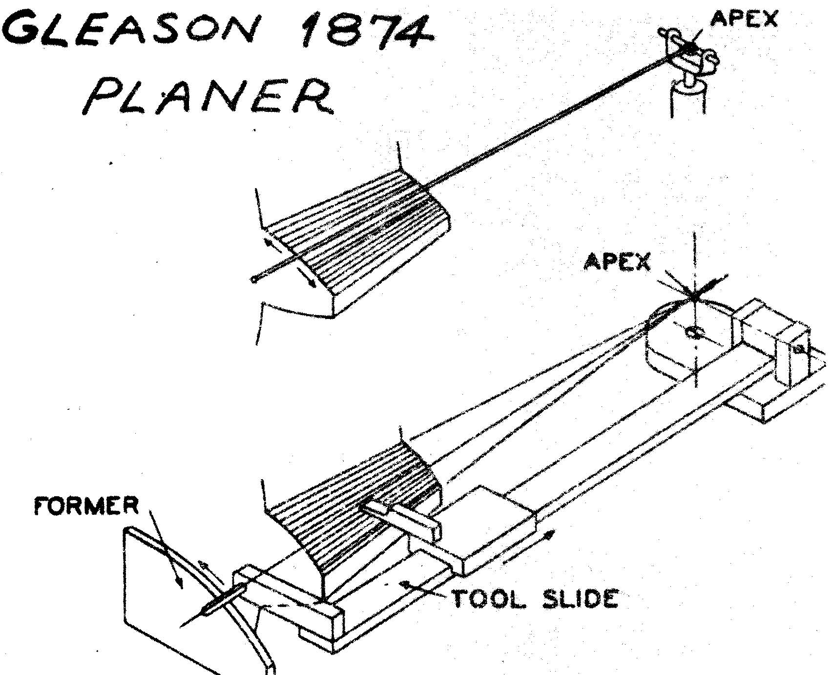
I have thoughts of making a small version of this machine so I can cut teeth in wax blanks. It is the simplest way I could make an accurate true bevel gear. Cast in nickel silver and covered in black grease would make a very convincing Shay gear.

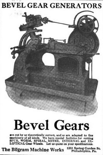
The next mathod to be avaible in the US was invented by Hugo Bilgram in 1884. This was a modified shaper with an attachment to roll the gear blank on a master cone that matched the pitch cone of the gear being cut. The shaper had a single tooth rack that cuts the gap. This ia a version from about 1900 with added automatic indexing. The first models had manual indexing and operation. This machine was designed for gears for chainless bicycles as this was all the rage at the time. I am not sure if these machines were ever made large enough for Shay gears.


I have considered making one of the attachments for my shaper but I soon sober up.

The final method was most likely not used at the Lima works but it could have been used by back shops near working Shays especially ones used in distant locations like Queensland.

The earliest mention of the parallel depth method I have found is in American Machinist Gear Book 1910 by Charles H. Logue. He was one of the editors of the American Machinist and gives two early 1891 and 1892 references of the method but states that the first practical method was published in the American Machinist 14 Jan 1909 by S. K. Allen and that is the method used in the book.

I have a full set of mod 0.5 gear cutters and I will explain the method and give it a try.
 
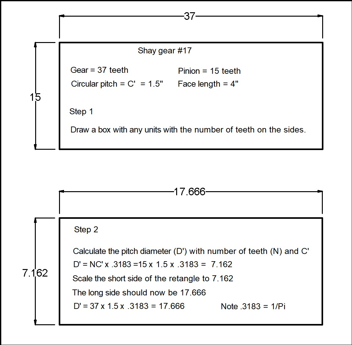
The gear used for the Dulong S/N 2091 was gear #17, Shay gears used circular pitch rules as this was common in the days when wood patterns were made. The circular pitch is the distance along the pitch circle/cone from one tooth to the next tooth this can be measured with a ruler. It would be more complicated to use a ruler with the more modern diametrial pitch rules. If you have a dimetrial pitch gear the layout method is the same simply use the DP rules.


I will be using spur gear rules and a drafting board (CAD) to to draw the tooth cross-section. This eliminates a bunch of formulas and you can see the math on paper. I prefer this method over formulas or spreadsheets that in my opinion obscures the design process and the beauty of gears which are simply math in metal.

Spur gear rules can be found in machinist books gear books and catalogs and on the web. Normally bevel gears are designed and measured at the big end this makes it a lot simpler to use a gear pitch gage to measure the pitch of the gear. It is really hard to get an accurate measurement with a gear pitch gauge on the small end of a beval gear.

First step is to draw a rectangle with the sides equal to the number of teeth on the pinion and the top and botom with the number of teeth on the bull gear.
Then we scale the side of the box using circular pitch rules for the diameter of the pitch cone at the big end this is the pitch diameter. With CAD the pitch diameter of the bull gear should automatically scale to match the formula.


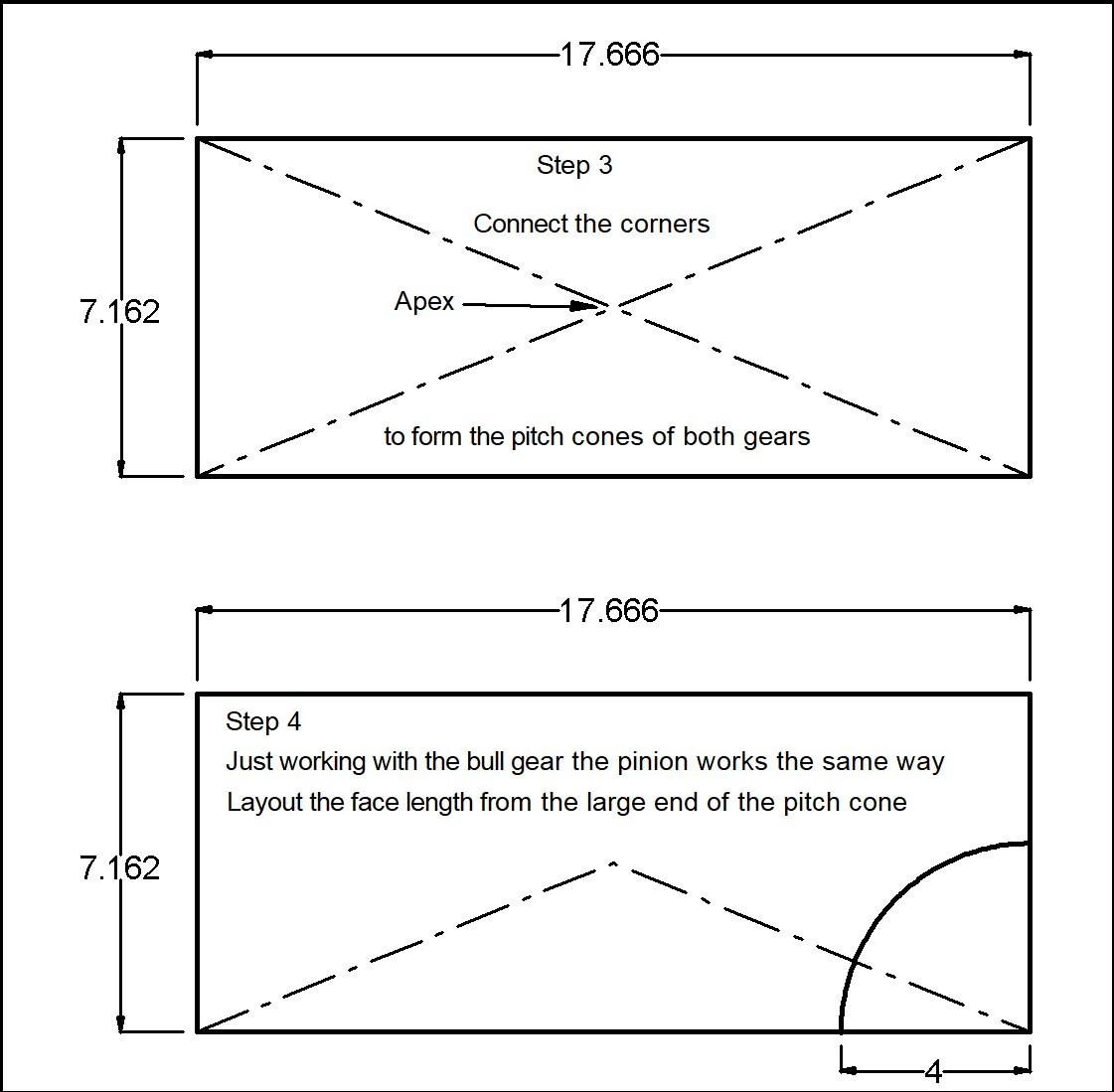
Now we draw the pitch cones. These are the theoretical cones that would work the same as the gear neglecting friction. This is the same as the pitch circle in a spur gear.


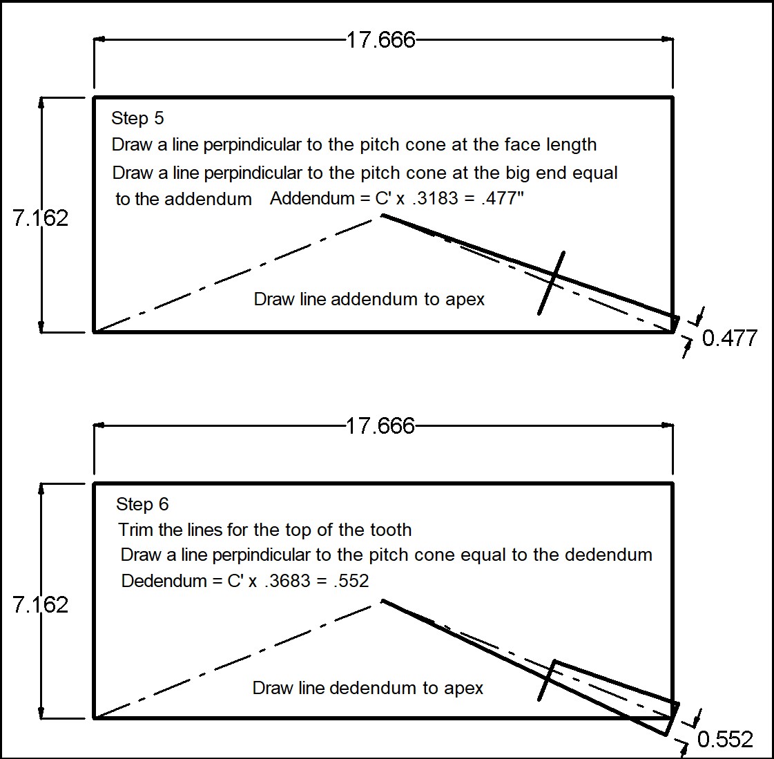
Now using the circular pitch rules for the addendum and the dedenum the parts of the gear above and below the pitch cone.


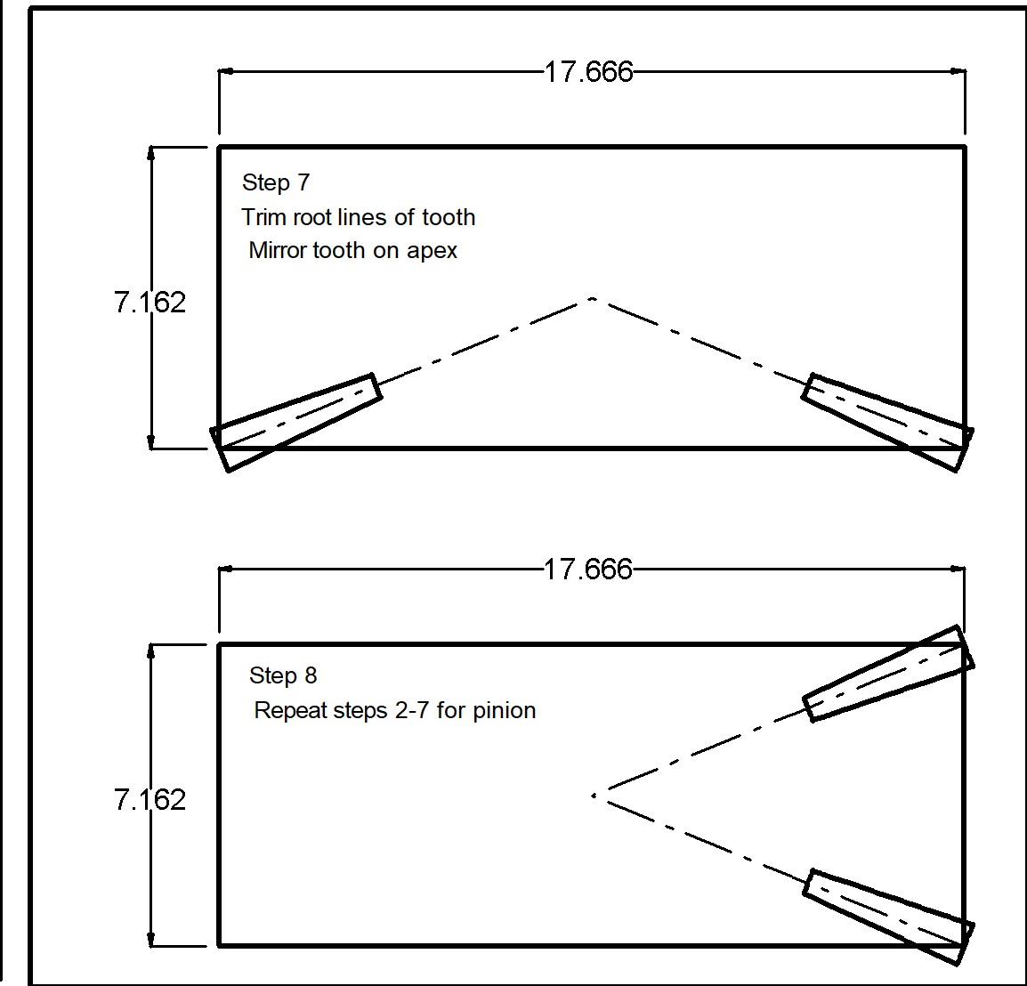
Cleanup and mirror the tooth profile and repete the process for the pinion.


In the next post I will scale the gear to 7/8" scale and design the parallel depth version.

If there are any questions or typos let me know.

Cheers Dan
ShaylocoDan

Offline crueby

  • Full Member
  • *****
  • Posts: 18665
  • Rochester NY
Re: Shay gears (parallel depth bevel gears graphical tutorial)
« Reply #1 on: September 07, 2020, 08:17:00 PM »
Dan - wonderful to see this brought together in one tutorial like this!    :popcorn: :popcorn: :popcorn:
Couple questions on this first installment:
In the first step, you calculate the Circular Pitch C and Face Length - what are the formulas for that?
How does the DP or Module of the cutters factor in, or is that in a later installment?
 :popcorn: :popcorn: :popcorn:

Offline Dan Rowe

  • Full Member
  • ****
  • Posts: 1170
  • Dripping Springs TX USA
Re: Shay gears (parallel depth bevel gears graphical tutorial)
« Reply #2 on: September 07, 2020, 08:29:50 PM »
Wow Chris you are fast....The circular pitch (C') and face length (F) and number of teeth (N) are the know facts of Lima gear #17.

Circular pitch, diametral pitch and module are all different rule sets for gears. Module is usually metric but the system can be used for nonmetric measurements. These rules sets are in books or catalogs. I have a little folder and I am not really sure where all my rule sets came from. My favorite gear book is Gear Design Simplified by Franklin D. Jones and it covers everything in this topic.

Cheers Dan
« Last Edit: September 08, 2020, 01:48:54 AM by Dan Rowe »
ShaylocoDan

Offline Dan Rowe

  • Full Member
  • ****
  • Posts: 1170
  • Dripping Springs TX USA
Re: Shay gears (parallel depth bevel gears graphical tutorial)
« Reply #3 on: September 07, 2020, 08:35:53 PM »
My study of the Lima Shay gear drawings led me to finding drafting tools to draw gears. The first one is a Robinson's template odontograph. This was used to draw the shape of the side or flank of a gear tooth.


This next tool is a Boorman's Patent "Anglegraph" from the instructions "An instrument for ascertaining the correct Angles of Bevel Gears, without any drawings, templates or gauges, or calculations, beyond the diameter of the pitch line."  The small print on the book cover says "All Communications to be addressed J, A, Boorman c/o Greenwood & Bately, Ltd., Albion Works Leads," I think I am a bit late for that but a web search for this tool leads nowhere.


I think both tools could have been in the Lima works drafting room.

Back to gear #17... I scaled the drawing to 7/8" scale the red line is a 12" line. The calculations for a parallel depth gear are made at the small end so now we calculate the diametral pitch of the small end knowing the number of teeth and the pitch diameter of the small end. The answer is about 49.5 I was originally going to use 48 DP but I could not find all the cutters I needed on ebay. The price of a full set of Mod 0.5 gear cutters was about $60. 48 DP and Mod 0.5 are very close to the same size so next step is to convert the red line to metric.


Cheers Dan

« Last Edit: September 07, 2020, 08:48:52 PM by Dan Rowe »
ShaylocoDan

Offline Dan Rowe

  • Full Member
  • ****
  • Posts: 1170
  • Dripping Springs TX USA
Re: Shay gears (parallel depth bevel gears graphical tutorial)
« Reply #4 on: September 07, 2020, 08:37:35 PM »
The true gear #17 was a cycloid tooth gear with slightly different rules for the addendum and dedendum, which made it just a tad bigger at the tips of the gears. I have never even considered making a true cycloid form as the cutters would have to be made in the shop.

The gear is scaled to metric dimnensions.


The green lines add about 0.01" or .25mm to the face of the small end and. This is the exact Mod 0.5 dimensions which I will use for the calculations. This green section will not be on the finished gear.

I use a program to design gears and it will generate .dfx and g code the new version will do printer friendly outputs. It will also draw cycloid gears but the watchmaker's form not the power gear form. If you are working with gears a lot it really is helpful.
http://www.delphusa.com/index.htm

Here is a screenshot for a Module (metric) 0.5 spur gear with 15 teeth and a 20 degree pressure angle. This matches the cutters I have.


Here is the 37 tooth gear.


I could have used the metric spur gear rules to calculate the dimensions but the program is simpler and no stupid math errors.

The addendum line and the dedendum line are both parallel to the pitch line with a parallel depth gear so here it is.


The red lines are the old gear. The new version is a bit smaller which is good as the trucks parts are already made and the gear clearence is close.

The next step is to select the cutter.

Cheers Dan
ShaylocoDan

Offline Dan Rowe

  • Full Member
  • ****
  • Posts: 1170
  • Dripping Springs TX USA
Re: Shay gears (parallel depth bevel gears graphical tutorial)
« Reply #5 on: September 07, 2020, 08:38:51 PM »
The face length of a Shay gear is just about the most important dimension of a model Shay truck because it is always seen in a clear right hand photo.


The gear rules compare the face length (F) to the pitch cone length (E). The rule for the modern Gleason system state that the face length should be about 1/4 E, and it should never exceed 1/3 E. No wonder I can not find a sutiable gear set!

The Shay gear is 0.42E which clearly exceeds the Gleason rule. No fixed rule is given for parallel depth gears, but they should not exceed 1/3 E. The reason given is the cutter is selected by the small end dimensions so excessive face length will make the form of the tooth at the big end stubby.


The drawing in the book is similar to the above drawing except that there is no Z dimension, here the first parragraph.

"NUMBER OF CUTTER."
    "Note: To determine the number of cutter to use (shape or profile number), first find the radius X  at inner ends of teeth; then determine the number of teeth of equal pitch on a spur gear of radius X, and select cutter to suit this number. (Some prefer the radius Y from the center-line to mid-section of tooth.) This radius Y may be obtained, accurately enough for practical purposes, by measuring a fairly accurate drawing."

The book then gives a fromula for calculating the radius at X, but as we already have a very accurate drawing we can simply measure the radius at X, Y, and Z. I used my gear program to draw the form cutters for Module 0.5, they are just below the red scale line. The cutter number at X the small end is 3. The number at Y is 4, and the number at Z is 5. I drew the green hatch to show the range of cutter number 4. It is clear to me that cutter 4 is the best comprimise and the big end should not be stubby.

Now on to the bull gear.


The cutter at the small end is 7 and the cutter at the middle and big end is nmber 8. The green hatch for cutter 8 is bigger than the section for cutter 7 so the best choice is cutter 8.

The rules given in this post are all from Gear Design Simplified by Franklin D. Jones. The method given in American Machinist Gear Book 1910 by Charles H. Logue makes the cutter number calculation at the middle of the gear face or at Y. This is the original method and it would have been used for replacement Shay gears if proper gear machines were not avaialble.

The next post will be how to cut the gear on a milling machine.

Cheers Dan
ShaylocoDan


Offline Dan Rowe

  • Full Member
  • ****
  • Posts: 1170
  • Dripping Springs TX USA
Re: Shay gears (parallel depth bevel gears graphical tutorial)
« Reply #7 on: September 07, 2020, 09:20:33 PM »
John, Many thanks, I found the first link but not the second one, now I have patent numbers and dates which are important facts.

Cheers Dan
ShaylocoDan

Offline Dan Rowe

  • Full Member
  • ****
  • Posts: 1170
  • Dripping Springs TX USA
Re: Shay gears (parallel depth bevel gears graphical tutorial)
« Reply #8 on: September 07, 2020, 10:39:27 PM »
Chris, when you were asking about bevel gears on your Mann Wagon build, I had an answer the next day but you had already cut the gears, so I took a bit more time to cover the subject. Here is a link to CP, DP  and Module rules.
http://www.linngear.com/wp-content/uploads/2013/06/Gear-dimension-calculation-tips_DP_CP_Mod.pdf

Cheers Dan
ShaylocoDan

Offline crueby

  • Full Member
  • *****
  • Posts: 18665
  • Rochester NY
Re: Shay gears (parallel depth bevel gears graphical tutorial)
« Reply #9 on: September 07, 2020, 11:36:09 PM »
Chris, when you were asking about bevel gears on your Mann Wagon build, I had an answer the next day but you had already cut the gears, so I took a bit more time to cover the subject. Here is a link to CP, DP  and Module rules.
http://www.linngear.com/wp-content/uploads/2013/06/Gear-dimension-calculation-tips_DP_CP_Mod.pdf

Cheers Dan
Great - thanks! Just saved that one away.  Like I probably will with this whole thread!   :cheers:

Offline jadge

  • Full Member
  • ****
  • Posts: 503
  • Cambridge, UK
Re: Shay gears (parallel depth bevel gears graphical tutorial)
« Reply #10 on: September 08, 2020, 11:10:33 AM »
Interesting exposition; thanks Don. I'm pleased to note that you mentioned Tregold's approximation.

There's nothing fundamental about the limits on the face width of a bevel gear. But there are some practical limits. In design terms as the tooth form gets smaller the load carrying capability also gets smaller and at some point extra face width simply doesn't add anything in terms of power transmission. In terms of manufacture whatever method is used the cutter must be able to pass through the small end. With a Gleason shaper that would be possible for relative large face widths although the tool would be fairly delicate. I've seen a Gleason bevel gear planer in action and had the details described at RAE Farnborough, but never used one in anger. In theory the parallel depth method shouldn't be bothered about face width, although I've never used the method. However the smaller the tooth form at the inner edge the greater the error in curvature at the outer end which would ultimately defeat the point of the large face width. I have cut bevel gears using involute cutters specifically for bevel gears, albeit some 45 years ago. The special cutters are designed to go through the small end of the bevel gear while having the curvature associated with the outer edge. There must be a limit on how small the inner edge tooth form can be, but I don't know what the cutter design limit is.

I'd second the book "Gear Design Simplified". When I designed the gears at RAE I borrowed a copy from the library, but have subsequently bought my own version.

These days I design in 3D CAD using pen, paper and formulae to derive the numbers. I'm no mathematician but even I can see elegance in the formulae. Once the planes are set up the design is fairly straightforward:


I design at 1DP and scale the drawing as a last operation. While I could make my own special involute cutters I find it easier to use the CNC mill to make the bevel gears in the first place. So it wouldn't be a problem having a large face width.

Andrew

RAE = Royal Aircraft Establishment

Offline PJPickard

  • Full Member
  • ****
  • Posts: 283
Re: Shay gears (parallel depth bevel gears graphical tutorial)
« Reply #11 on: September 08, 2020, 11:55:30 AM »
Dan,
Nice discussion and I have ordered a copy of the book. As for the real engines, I think it is mentioned in the Climax book that they were used as cast. Years ago I was at Cass (back when they let you walk around the shops and yard) and WM #6 was outside the shops. I guy was using and angle grinder to shape a gear that they had just built up with weld. That surprised me, but on further reflection I knew that the Cass shop had no way(well ,no easy way) to machine the gears. Still seemed kinda undignified to be using an angle grinder on the last Shay ever built!

Offline Dan Rowe

  • Full Member
  • ****
  • Posts: 1170
  • Dripping Springs TX USA
Re: Shay gears (parallel depth bevel gears graphical tutorial)
« Reply #12 on: September 12, 2020, 09:12:10 PM »
I'm pleased to note that you mentioned Tregold's approximation.

Andrew, there is no mention of Tredgold's approximation in the text!!!! I have read more than several books about bevel gears and I remember that some of them mentioned Tredgold's approximation but even after a reread I did not really understand it. Old textbooks can sometimes be a bit hard to wade through.

I checked the web and found a better explination.

"The form of teeth formed based on Tredgold's Approximation depends upon the slant height of the back cone (not on the radius R). A sphere is approximated between the back cone and pitch cone as shown in the figure below. The back cone is forming the teeth of the equivalent spur gear."


https://www.ques10.com/p/47776/virtual-no-of-teeth-of-bevel-gear-by-tredgolds-a-1/

Now I see that the method I used to find the number of the gear form cutter was Tredgold's approximation.

This makes me question my method for drawing 3D bevel gears. I think I should be using Tredgold's approximation to choose the form of the involute curve and apply it to the back cone.

The template used for a Gleason template planer should also use Tredgold's approximation calculated at the location of the template if my thinking is correct.

Did you have to file the teeth when using the special thin bevel gear cutter? My books on the subject say the method requires filling.

Thanks for the tip.

Cheers Dan
« Last Edit: September 13, 2020, 02:11:28 PM by Dan Rowe »
ShaylocoDan

Offline Dan Rowe

  • Full Member
  • ****
  • Posts: 1170
  • Dripping Springs TX USA
Re: Shay gears (parallel depth bevel gears graphical tutorial)
« Reply #13 on: September 12, 2020, 09:19:09 PM »
Years ago I was at Cass (back when they let you walk around the shops and yard) and WM #6 was outside the shops. I guy was using and angle grinder to shape a gear that they had just built up with weld. That surprised me, but on further reflection I knew that the Cass shop had no way(well ,no easy way) to machine the gears. Still seemed kinda undignified to be using an angle grinder on the last Shay ever built!
Good story about Cass. I did not know that the shops were off limits these days. I have not been there for several years. My favorite visit was when the #5 was being overhauled. There were Shay parts all over the place and the steam engine was in a bunch of pieces. This was before cell phones so I rushed to the gift shop to buy a disposable camera, unfortunately I am not good with photography and not one photo in the whole roll was any good just a blur.

Cheers Dan
ShaylocoDan

Offline jadge

  • Full Member
  • ****
  • Posts: 503
  • Cambridge, UK
Re: Shay gears (parallel depth bevel gears graphical tutorial)
« Reply #14 on: September 13, 2020, 08:18:02 PM »
Did you have to file the teeth when using the special thin bevel gear cutter?

Yes, I did have to file the small end of the teeth to make them curve a bit more. The gears are quite small, 20 teeth and 20DP. So only a quick pass with a file was needed. I also ran the gears in with grinding paste after case hardening, driving them with an electric drill. It got rather exciting when the sliver of aluminium I was using to spread the paste got caught in the teeth.

You are correct, the pattern for a Gleason bevel planer should take into account Tregold's approximation.

When I create a bevel gear in CAD I place the involute profile as modified by Tregold's approximation on the back cone. The sketch is then lofted to a point at the origin to get the tooth, which can then be replicated in a circular pattern.

Andrew


SimplePortal 2.3.5 © 2008-2012, SimplePortal