Before I continue the build some new information has surfaced which puts the original article at a some what earlier date of 1881 (Thanks Pat)
The last few parts comprise the head and valve assembly.
As mentioned at the start the article calls for a cast head with passages cast in though the detail was not really clear enough to see exactly what was intended and the overall shape was quite boxy. I drew up something a bit more appealing to my eye and used the CNC to translate that image into cast iron. Without removing the partially machined head from the 5C block I transferred to the manual mill to drill and ream for the sleeve and drill & tap the inlet exhaust pipe connections.

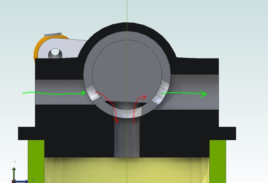
Some more doodling with Alibre came up with a valve design that I thought would work, here is a section through the head. There is an inserted sleeve that has what would be the port faces on a slide valve engine milled into it, drilled passages down into the cylinder. There is then a stainless steel spindle with a flat milled onto it that will open and close the ports and connect the open one to the cylinder as it is rocked by the eccentric rod.
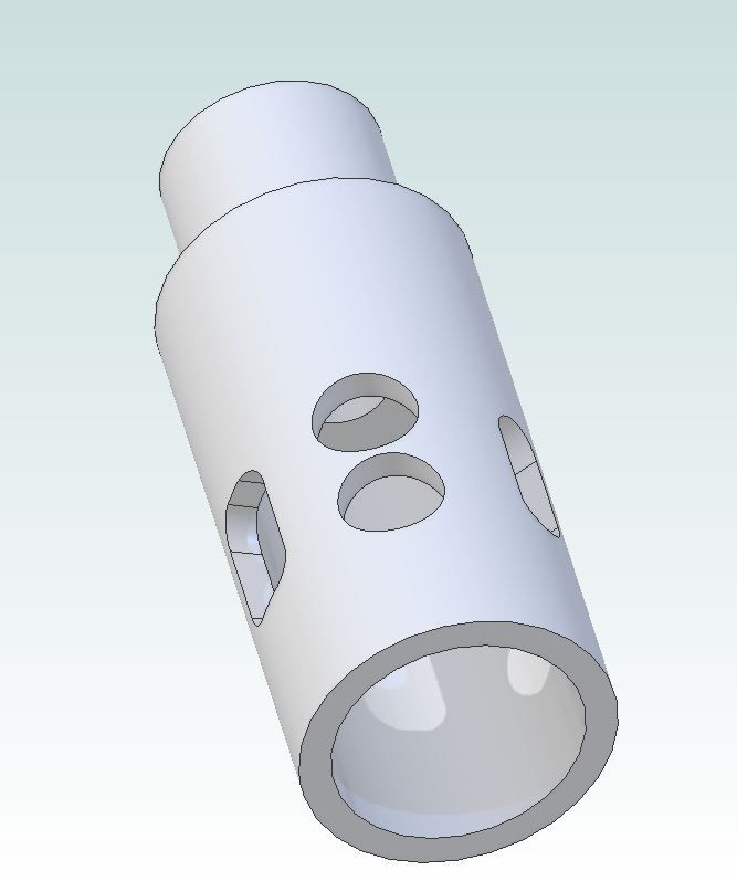
This is the sleeve with the larger exhaust slot on the left
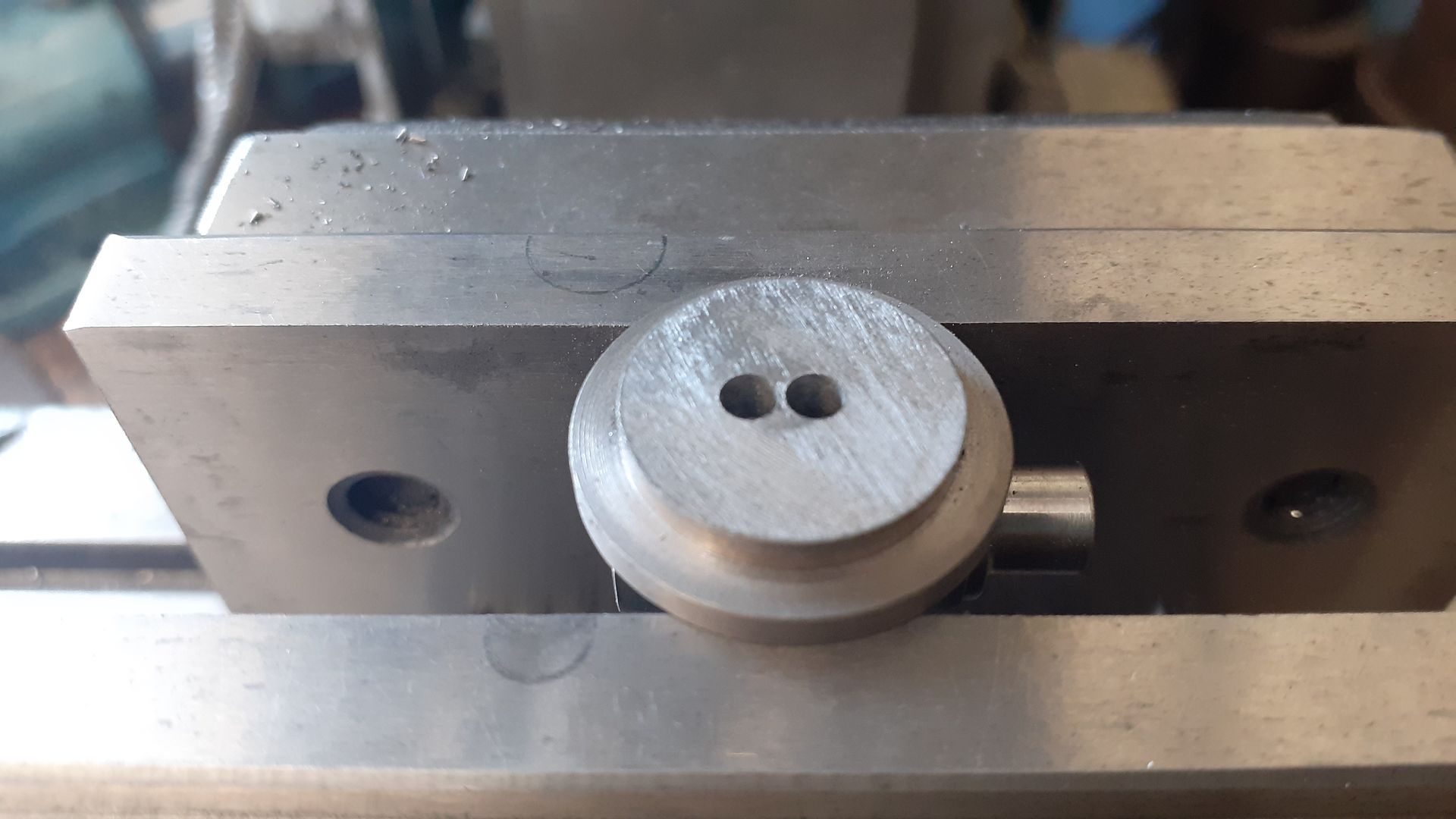
Once the sleeve had been Loctited into the head the two holes were drilled
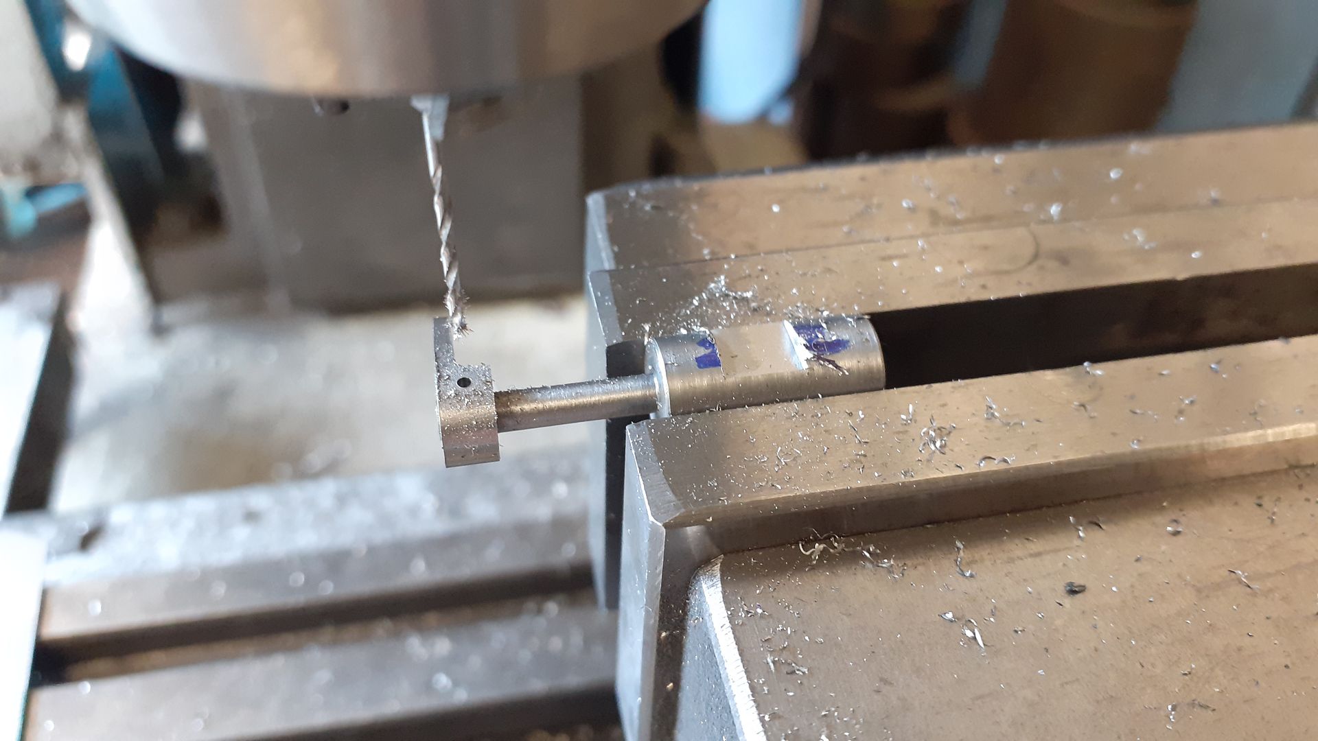
This pic shows the valve spindle having had it's flat milled a 1mm hole was drilled through it's spigot and the actuation arm so they could be pinned together
From an early stage I had decided to leave this engine in bare metal which I did with the exception of the "cast" surface of the flywheel which was done in a Rustoleum cast iron effect paint. I did think of bead blasting it but it would have been prone to rust so went with the paint. A piece of mahogany that I took out of a clients 110yr old house provided the base.


