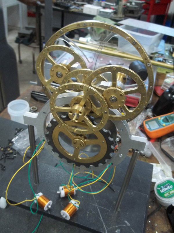
Finished gluing in the rest of the magnets and did a test assembly of the gear mechanism to test. Other than the large wheel, all the others seemed to hook up properly. The large wheel rim is separated too far from its engagement partner by about 1/8". This will be easy to adjust by facing off from its hub to move it closer. After disassembly, I need to finish up a few things before an actual run test.
1) Loctite the intermediate and minute hand hub to their respective wheels. They're currently a tight slip fit and can slip under any pressure.
2) Drill the end of the rotor shaft to accommodate attaching the second hand.
3) Machine the relief groove in wheel D, which I overlooked originally. My CNC mill is down for repairs, so I'll likely use the lathe or the rotab.
I found that the assembly should go like this:
1) Attach the bearing carriers to the frames.
2) Assemble the secondary frame completely but do not attach to the main frame as yet.
3) Assemble the rotor shaft components onto the main frame - rotor, damper, and magnet wheel.
4) Add front intermediate shaft and wheels to the main frame.
5) Attach secondary frame to main frame.
6) Finally add damper assembly and coils.
I found that using 82 degree flat head screws to attach the three wheels with the hex holes is probably not optimal. A countersunk socket head works fine, and there is no clearance problems. The issue with the flat screws is that the theoretical depth of the 2-56 head is .051". With a 1/16" hex boss on the shaft and a 1/8" thick wheel, it is quite tricky to get a precise countersink. Too deep and the wheel is loose, and too shallow the head protrudes. Since the countersink is on the opposite side from the magnet pockets, a second op is needed on these wheels. If the countersink is off center, even is the depth is correct, the screw head can cause the wheel to be cocked.


