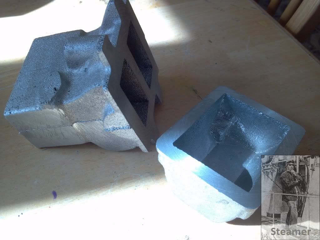
OK I made a start on the block castings by facing the flange to a finished thickness and flat. I mounted the block in a 4 jaw chuck and set up the casting so that the flange was an even thickness all the way around. I then set up the sump casting and did the same thing.
Easy Peasy...
I then faced the top of the block to +.040" by setting it up in the mill and facing it dead parallel to the base flange.
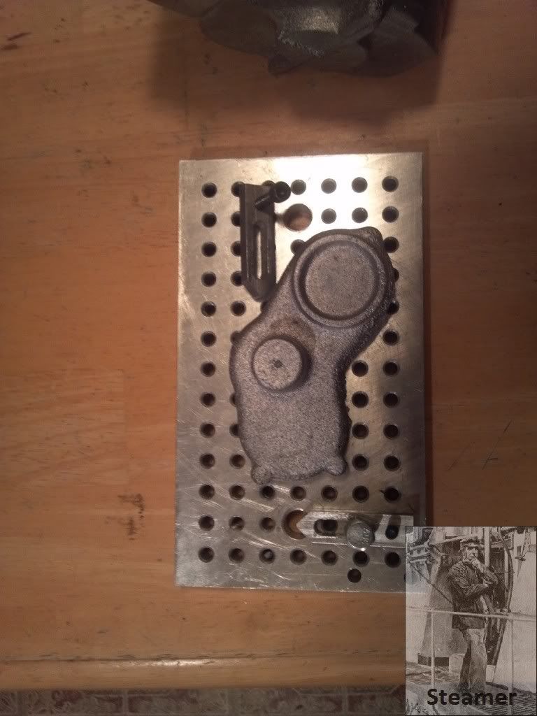
Next came the initial machining of the timing cover.
I set the cover up in my lathe on a fixture plate mounted on a faceplate....I love faceplates! I have several of these fixture plates and they are nothing more than a piece of aluminum plate with some holes in them It helps if their squared up as it makes it convienent to shift from machine to machine....but it's nothing fancy by any means. I made the straps too, and the fixing bolts are 1/4-20.
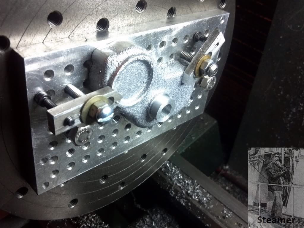
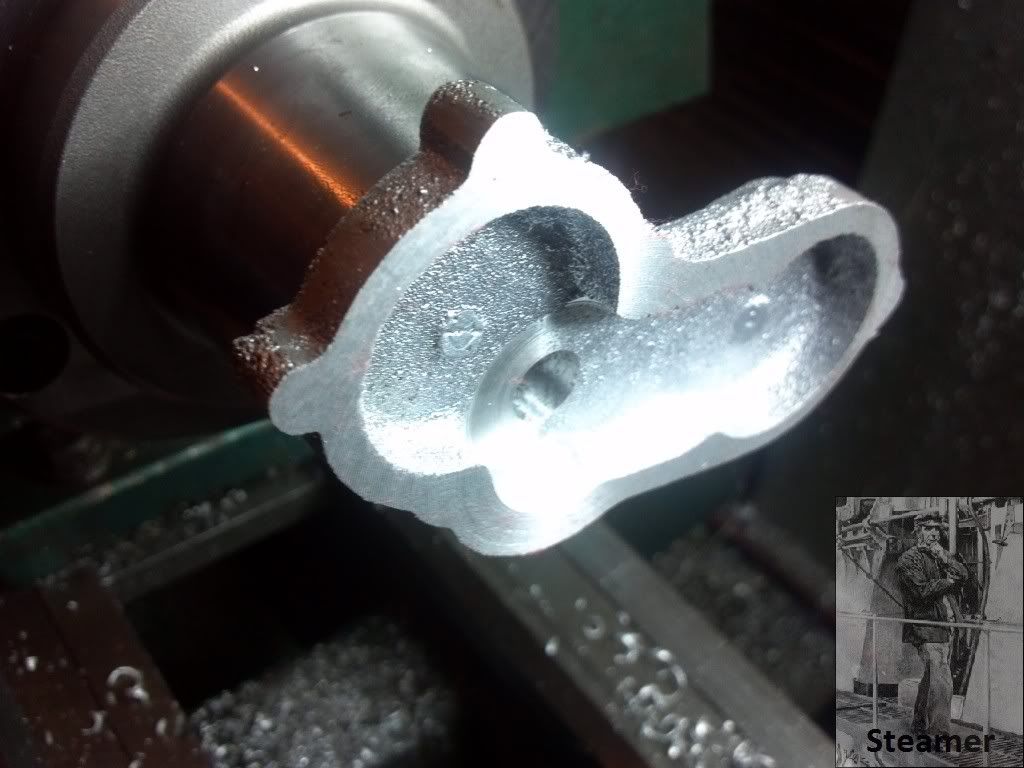
After a quick work over with a file to get the back somewhat flat, I mounted this all up and centered the casting boss in the lathe and then proceeded to machine the front boss and bore in one setup.
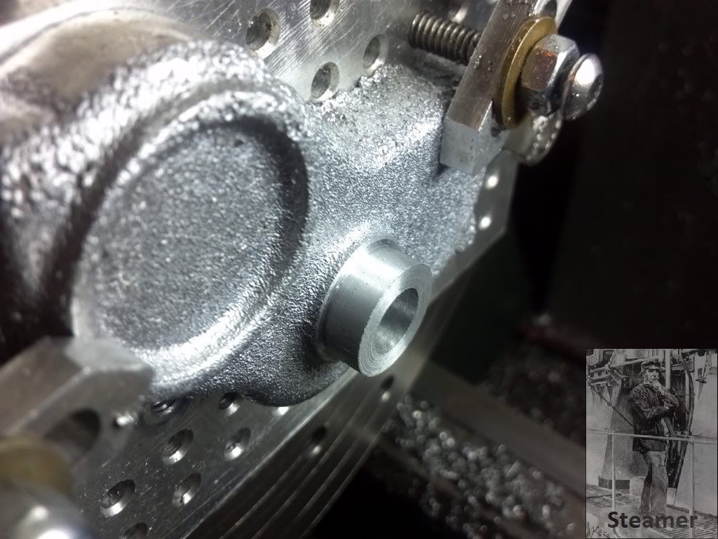
After that I mounted my collet chuck and held the casting by the finished boss faced the back side and cleaned up the bore of some sand splatter...
Now I'm approuching these parts this way, because of the picture on the first page of this thread. The Oil pump is WAY over constrained....TOO MANY DATUMS!
3 castings locate the pump in it's entirety.....The most problematic is the gear case cover. It is fixed by the bushing in the just completed bore that mates with the crankshaft. There is no float there anywhere. It also locates 1 side of the oil pump via an eccentric spigot. The other side of the pump is located by a concentric spigot on the other side of the pump where it's mounted into the sump. This is of course, located by the block!.....YUCK!
The only way I can figuire to machine this is to do it all "in situ" using toolmakers buttons I'll offer that I don't have DRO's on any of my machines. The Southbend will get it eventually....but that's another project!
So this is the plan.
Set up the block and bore it for the crankshaft/bearings
Mount the sump and face the ends parallel to eachother and square to the crank.
Dismount, and using toolmakers buttons, locate all the various gears in mesh on the front of the block adjusting as I go to get good mesh.
Set up on the block and locate the timing case with the crankshaft bushing.
Drill and tap the mounting holes for the timing case.
Set the block/sump assembly back up on the lathe locating on the cam shaft center.
Bore the block for the camshaft bearings.
Mount the timing case
Face and bore the distributor boss concentric with the crankshaft
Dismount the timing case.
Set up on the idler gear location
More the block for the idler gear pin.
Set up on the oil pump drive gear location
Bore the sump for the drive gear shaft bushing
Install the previously made bushing
bore to size.
Install the timing case.
Bore the case undersize to the pump pilot bearing diameter (.250)
Lightly face the timing case in the area of the pump mount.
Temporarily install the pump body on the case with small screws
Sweep the eccentric pump body in on center of the swing of the lathe.
Remove the pump
Bore the timing case spigot which is now eccentric to the pilot bearing diameter.
Tap the final holes in the case.
........piece of cake!.......
What could go wrong?

Dave


