Hi everyone
Continuing on with the exhaust valve chest, exhaust valve and related parts; I would like to try to finish this assembly before I move on to the piston, rod, and head.
My plan thus far is to deviate from the plans somewhat; Im working to keep everything proper as far as the prototype goes. I decided not to use a couple of iron castings that came with the kit; the first one is the top support; this part guides the bottom end of the valve and also serves as a pivot for the top end of the swing arm. The reason is, first I like the look of the brass parts on the original engine; and second I dont plan (at this time) to use the governor and I didnt want to hack the governor latch mount off of it incase I change my mind later.
I modeled the top support in Alibre and carved it out on my CNC here at home. It is only a 2 axis so there was a lot of hand work involved.

Here is the basic profile being cut from brass bar stock.

The boss for the swing arm pivot is machined as it is centered in the support but not as thick.

After the top side was machined the part was turned over and the bulk of the excess material removed from one end (notice the valve guide was reamed in the previous step).
Using the valve guide as the datum the bottom side of the pivot boss is machined.
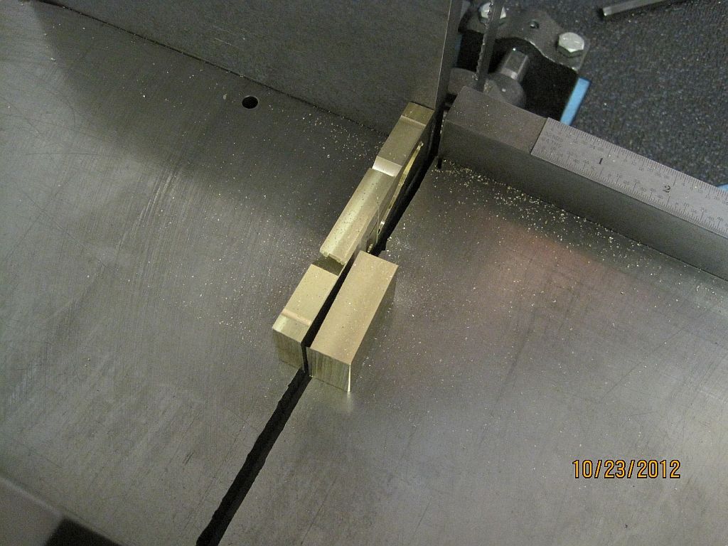
The rest of the excess material is removed in the band saw.

After the support is brought to proper thickness the excess junk will be cut away.
I got carried away and didnt take very many pictures of this process but after the machine work was completed quite a bit of time was spent with files and sandpaper getting an acceptable shape.

I also got carried away and neglected to leave enough material for the bosses on the top and bottom of the valve guide; those were turned up and silver soldered in place.
Now the is set up in the mill to fit the upper and lower swing arm supports along with drilling and taping the valve chest mounting holes and drilling exhaust port. I altered the shape of the bottom support bracket from the print just a little; all the brackets I have seen pictures of are a little different shape and style from one to the other. I think the horsepower of the engine and possibly age determined the style of the support. I chose to model the simple right angle support with its mounting holes in line above each other.

Here the body casting along with the cylinder is set up in the mill and dialed in using the crank bearing for the datum. Every thing is based off of the center line of the engine.

The upper support mounting pads are machined to the final height; this is based on the valve chest mounting boss. I set my valve chest and upper support on the surface plate and measured the valve stem centerline. As it turns out on my engine they are in the same plane; so this is what I cut the pads to.
I will remove .01 form the valve chest later to accommodate the copper valve chest gasket thickness.

The pads are spotted, drilled, and tapped for the upper support.

The exhaust port is drilled into the cylinder.

Finished!

I didnt take and pictures of the machining but here are the exhaust valve chest studs installed in the cylinder.

And with the valve chest and proper nuts installed.
Next I will go over the swing arm and lower support machining.
Thanks for checking in.
Dave


