Thanks for all the kind words guys. Other than some test pieces this is my first riveting project; so it was a learning experience for me.
Maury the tank must look bigger in the pictures than it really is. It is 4 X 7and 5 tall. I didnt want it to overpower the engine and pump, so it is a much smaller scale version of what it should have been. If it were full size it would have been almost as tall as the engine.
Kim, I learned a lot of what I know about riveting from your Steam tractor build.

While doing some test parts I soon realized the creating a full domed head was going to be quite a challenge. I experimented with different lengths and determined that the full dome head took enough force to form that is was going to distort my relatively thin parts. All of the formed heads are hidden from view so I was ok with not going down that road. Looking at the picture of the tank I was using as a guide it appeared that they just smashed the rivets flat. I think this may be common practice for tinners rivets. I did find that once I got going that by reducing the length of the rivet I was able to achieve a nice, more flat dome; so this is what I went with. On the tank bottom I did just squeeze the rivets flat. This is not an easy area to work in and I guess that if I had taken the time to make a rivet squeezer I may have been able to dome the heads but I would really like to get this project completed someday. I have some pliers that came from my granddad (Plierwrench brand) that the jaws open and close parallel to each other on a rack and pinion. I used these to squeeze the bottom row of rivets; using a snap to protect and form the factory head on the outside and flatten the head on the inside. I will post a picture if you are interested in seeing them.
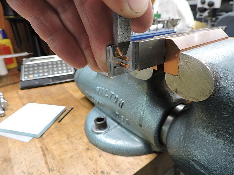
The fixture I used to cut the rivets is nothing more than a piece of CRS milled to the desired thickness with a couple holes drilled in it. A sharp wood chisel was used cut the rivets while using a finger to hold them in place
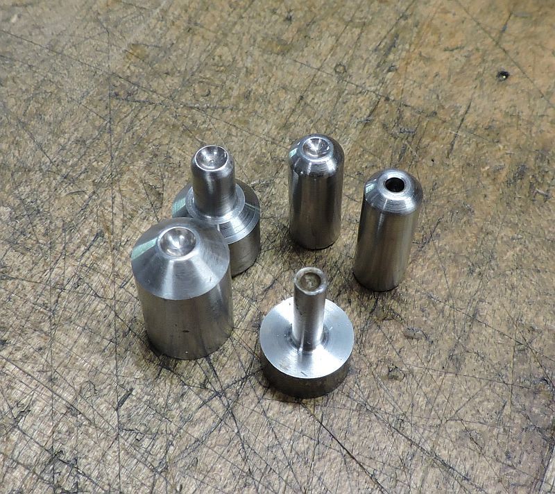
The snaps (I guess that is what you call them) were turned from drill rod and used unhardened. The annealed copper rivets are very and easy on tooling. Some of them had to be modified for clearance.
These are the ones that got pounded on with a hammer.
The business end; the one with the hole was used to make sure the rivet and parts were all where they needed to be. After using this punch or snap I would use the small ball peen hammer to upset the head and tighten everything. Then use the dome snap to finish it off.
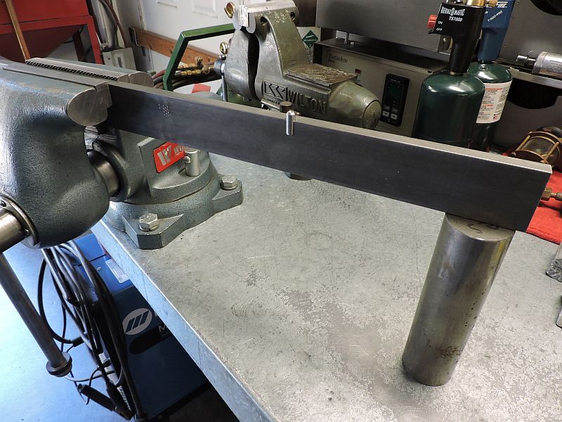
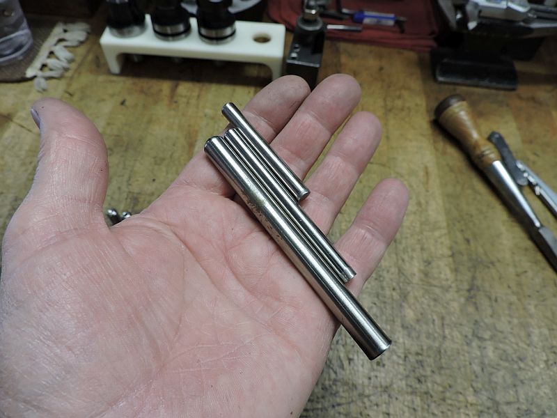
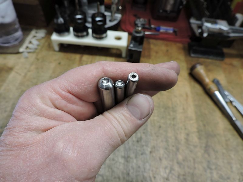
This is my lash up that I used to set the rivets on the inside of the tank.
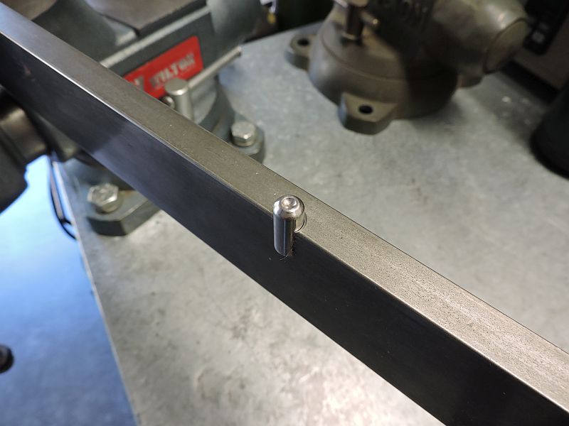
The snap was offset enough to allow access to rivets that are quite close to the corner. As you can see in the pictures of the snaps there is also one with a hole that was used first.
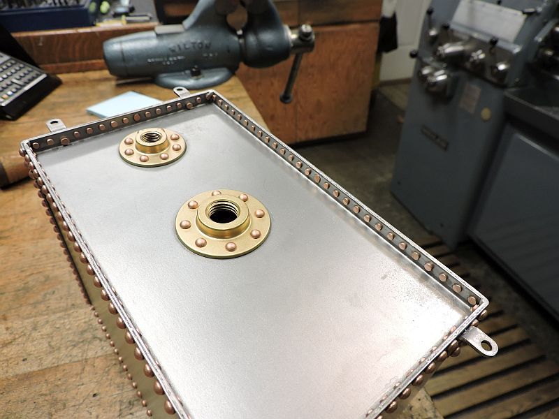
Here is a shot of the tank bottom; you can see how the rivets were flattened on the inside. When starting out I would use a tiny pair of parallel machinist clamps to draw the metal together. One clamp on each side of the rivet; this was repeated until enough rivets were installed to squeeze everything up tight. The rivets were first set with a long pin punch then finished up by squeezing with the Plierwrench.
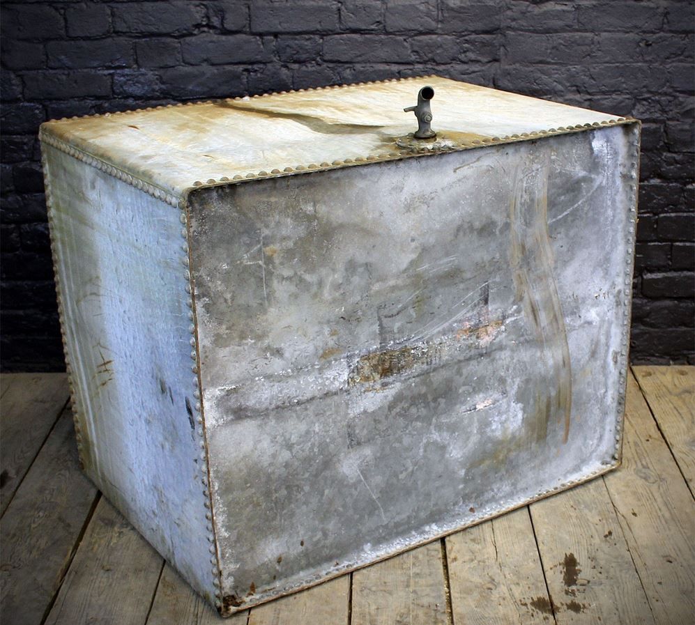
This is a picture of the tank that I was kind of using as a pattern. If you look close you can see that it appears the rivets on the bottom appear (at least to me) to be flat on the inside.
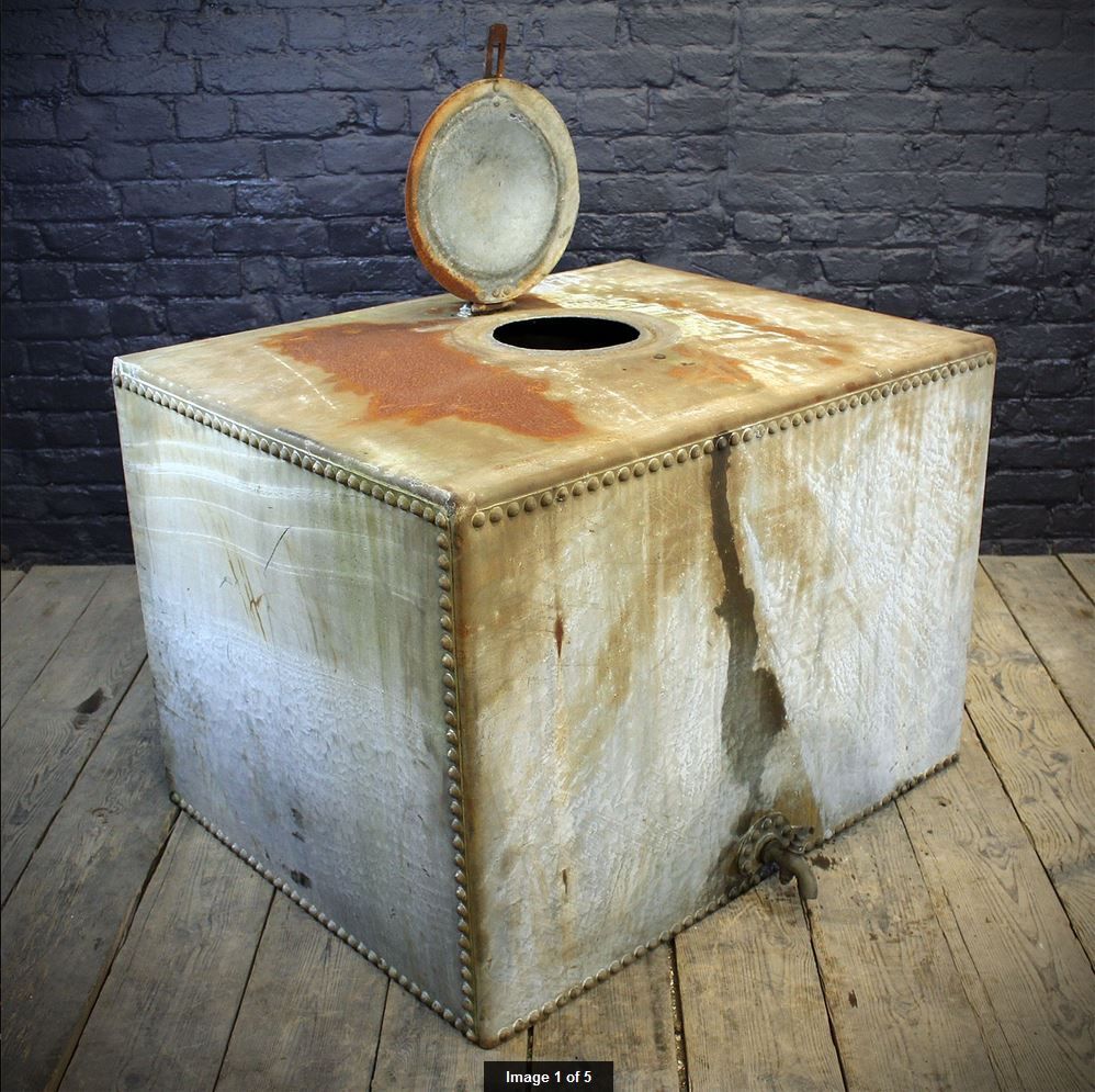
One more shot of the original tank.
Thanks again for all the nice comments.
Dave


