Author Topic: Pacific Vapor Engine from Morrison & Marvin Castings  (Read 216295 times)

Offline Jo

  • Administrator
  • Full Member
  • *****
  • Posts: 15306
  • Hampshire, england.
Re: Pacific Vapor Engine from Morrison & Marvin Castings
« Reply #210 on: August 14, 2013, 07:50:43 AM »
Dave,

Looking at your excellent bit of machining to cut that plate to size can I assume that you are using CNC?  If I had done it on my mill I would have looked to cut most of the central area out square to the mill's bed then used the DRO's radi function to turn the curves on the inner and outer edge. I guess that it would have been just as easy to mill the curves using a rotary table, but I still have to be brave enough to learn how to use that  :ShakeHead:.

And  :headscratch: I must ask what is that piece of bent steel hiding under the plate in the second photo?

BTW: Thanks for showing a picture of a ruler with the base. It is handy for those of us following along to be reminded the size of other engines from time to time  ;).

Jo
Enjoyment is more important than achievement.

Offline Stuart

  • Full Member
  • ****
  • Posts: 1785
  • Tilchestune UK
Re: Pacific Vapor Engine from Morrison & Marvin Castings
« Reply #211 on: August 14, 2013, 08:19:23 AM »
Jo I think its a bit of spring steel like a hair grip in reverse to hold the parallels out to the vice jaws .

I whole hardly endorse your comment with ref to a rule ( scale for the US ) to be included in photos as we all build in different scales sizes it help to visualise the model

Dave that is some seriously good work you have done on this project , make my work look like I have machined it wit a rust nail for a cutter


look forward to see it when it is completed

Stuart
My aim is for a accurate part with a good finish

Offline b.lindsey

  • Global Moderator
  • Full Member
  • *****
  • Posts: 13860
  • Dallas, NC, USA
    • Workbench-Miniatures
Re: Pacific Vapor Engine from Morrison & Marvin Castings
« Reply #212 on: August 14, 2013, 01:07:00 PM »
Amazing work Dave. Those castings look to be really high quality as well...the crisp cast in lettering, etc., and not just on the base but on all the castings shown throughout the build. Still following along and looking forward to more!!

Bill

Offline Dave Otto

  • Full Member
  • *****
  • Posts: 4712
  • Boise, Idaho USA
    • Photo Bucket
Re: Pacific Vapor Engine from Morrison & Marvin Castings
« Reply #213 on: August 15, 2013, 07:29:14 PM »
Thanks of all the kind words guys.

Jo, Stuart is correct; that is a parallel keeper that I purchased years ago from Rutland, a tool supplier here in states.

When you use the radius feature of your DRO can you control the scallop size (the little bump left between the cuts)? I program and run a NC sheet metal punch at work and it has the ability to nibble which I guess would be about the same a the arc feature of your DRO. Typically the scallop size we use is .002" on radius cuts.

Thanks again,
Dave

Offline Jo

  • Administrator
  • Full Member
  • *****
  • Posts: 15306
  • Hampshire, england.
Re: Pacific Vapor Engine from Morrison & Marvin Castings
« Reply #214 on: August 15, 2013, 08:52:05 PM »
Yes the scallop size is fully programmable as one of the inputs. but when you are manually doing each X/Y location it can get tedious  :-\ so using as large a cutter as you can get away with means you can use a larger scallop measurement.

Jo
Enjoyment is more important than achievement.

Offline Dave Otto

  • Full Member
  • *****
  • Posts: 4712
  • Boise, Idaho USA
    • Photo Bucket
Re: Pacific Vapor Engine from Morrison & Marvin Castings
« Reply #215 on: September 09, 2013, 11:24:26 PM »
Hi everyone

I was able to spend some time late last month and got the engraving done on the Lunkenheimer grease cups. Armed with a new spring-loaded diamond engraver from 2L and some encouragement from Gary Hart, I gave it a try.

The geometry was created in Solid Works using a photo of the original as a drawing template; then on to the CAM program to create the tool path.
After a few test cuts I had the feed and speed pretty well dialed in; I’m pleased how good they came out. Because the diamond displaces the material instead of cutting it the bumps needed to be carefully sanded off.

The letters are approximately .03” tall and ended up being about .005” deep.

Here are a few pictures, one showing the original I used as a pattern.


This was a fun little task and I already have an idea where I will use it next.


Thanks for checking in,
Dave


Offline Don1966

  • Full Member
  • *****
  • Posts: 6818
  • Columbia, MS
Re: Pacific Vapor Engine from Morrison & Marvin Castings
« Reply #216 on: September 10, 2013, 01:29:43 AM »
Beautiful work Dave and glad to see you get some time in.

Don

Offline Jo

  • Administrator
  • Full Member
  • *****
  • Posts: 15306
  • Hampshire, england.
Re: Pacific Vapor Engine from Morrison & Marvin Castings
« Reply #217 on: September 10, 2013, 05:47:38 AM »
Very nice  :ThumbsUp: That is one thing that Soild Works will allow you to draw that Alibre won't  :(

Jo
Enjoyment is more important than achievement.

Offline swilliams

  • Full Member
  • ****
  • Posts: 896
  • Canberra Australia
Re: Pacific Vapor Engine from Morrison & Marvin Castings
« Reply #218 on: September 10, 2013, 07:26:35 AM »
Excellent Dave, the black paint is a nice touch too

Steve

Offline b.lindsey

  • Global Moderator
  • Full Member
  • *****
  • Posts: 13860
  • Dallas, NC, USA
    • Workbench-Miniatures
Re: Pacific Vapor Engine from Morrison & Marvin Castings
« Reply #219 on: September 10, 2013, 02:25:47 PM »
That is sweeeeet Dave. Looks every bit like the original and will make a fine detail addition to an already beautiful model !!

Bill

Offline vcutajar

  • Full Member
  • *****
  • Posts: 2555
  • Marsascala, MALTA
Re: Pacific Vapor Engine from Morrison & Marvin Castings
« Reply #220 on: September 10, 2013, 07:20:20 PM »
Amazing Dave.

To get the black lettering, did you paint the engraving and then sand the excess away?

Vince

Offline metalmad

  • Full Member
  • ****
  • Posts: 687
  • Australia Skype - metalmad11
Re: Pacific Vapor Engine from Morrison & Marvin Castings
« Reply #221 on: September 12, 2013, 11:47:42 PM »
Hi Dave
Every time I look at your work, I wonder just how you get your amazing finish!  :praise2: :praise2:
Pete
« Last Edit: September 16, 2013, 07:44:59 AM by metalmad »
A little bit every day, sometimes the same little bit

Offline Dave Otto

  • Full Member
  • *****
  • Posts: 4712
  • Boise, Idaho USA
    • Photo Bucket
Re: Pacific Vapor Engine from Morrison & Marvin Castings
« Reply #222 on: September 16, 2013, 12:24:18 AM »
Thanks for the comments everyone and also checking in on my slow progress.

Vince; sorry I forgot to answer your question. The black in the letters is not paint it is a product from Birchwood Casey CO. called brass black. It is a thin watery chemical that was applied to the letters with a cotton swab then rinsed with water.  The top was sanded in the lathe with 800 grit to remove the excess black around the letters.

Thanks again,
Dave

Offline Dave Otto

  • Full Member
  • *****
  • Posts: 4712
  • Boise, Idaho USA
    • Photo Bucket
Re: Pacific Vapor Engine from Morrison & Marvin Castings
« Reply #223 on: September 16, 2013, 03:02:23 AM »
Hi Everyone
I finally was able to carve out some time to work on the piston trip ignitor.  The cylinder casting had bosses cast for the feed throughs; but the way my cylinder finished up I wasn’t completely happy with the position of the boss relative to where the holes should be.

My original plan was to completely remove the boss and counter bore the cylinder to create a flat area for the insulator to sit. I actually did this but then wasn’t overly happy with the way it looked. Part of the reason was I sized the counter bore to fit some mica washers I had on hand; and after the fact the scale just wasn’t correct. So after thinking about it for a few days I decided to go ahead and replace the bosses.

 The new bosses were turned and then pressed and Loctited into the counter bore. A small fillet was added with the Devcon and I was starting to feel better about how it was all looking.  I have seen these engines both ways (with the counter bore and also with the boss) so I would say either way could be correct.

The Devcon I have been using is called Plastic Steel Putty (A) it is a steel reinforced epoxy; the mix ratio is 9:1 by weight or 2.5:1 by volume. This gives you some idea of the amount of steel filler that it has in it. It is not cheap but a much better product than JB Weld types of epoxies.
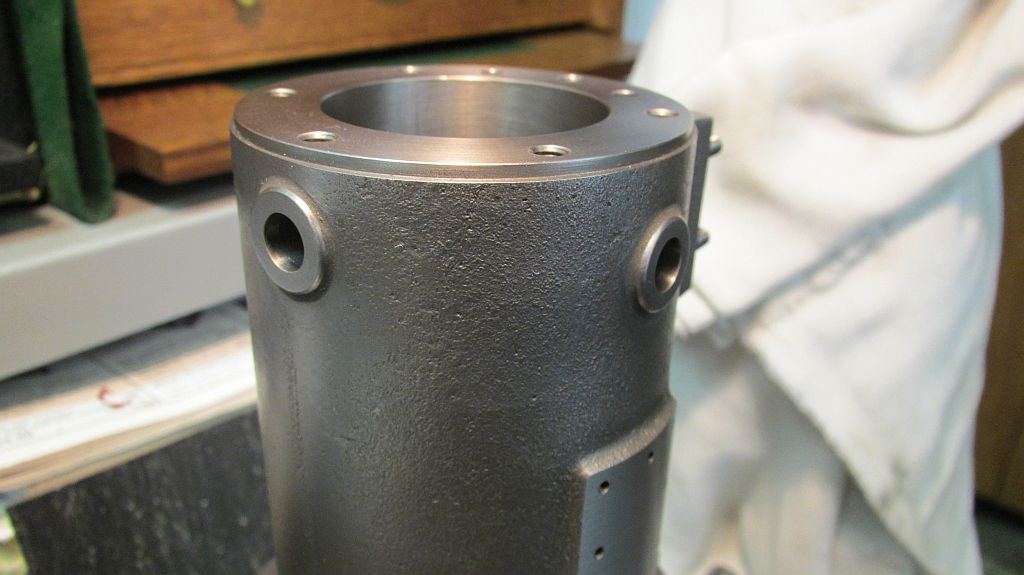

Here are the two new ignitor bosses.
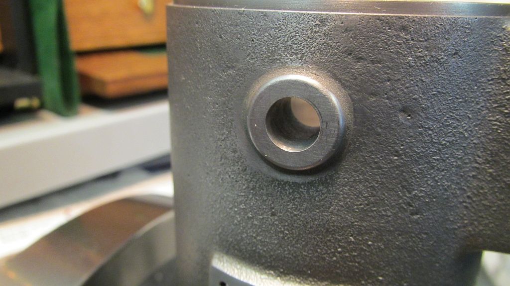

And a close-up shot.
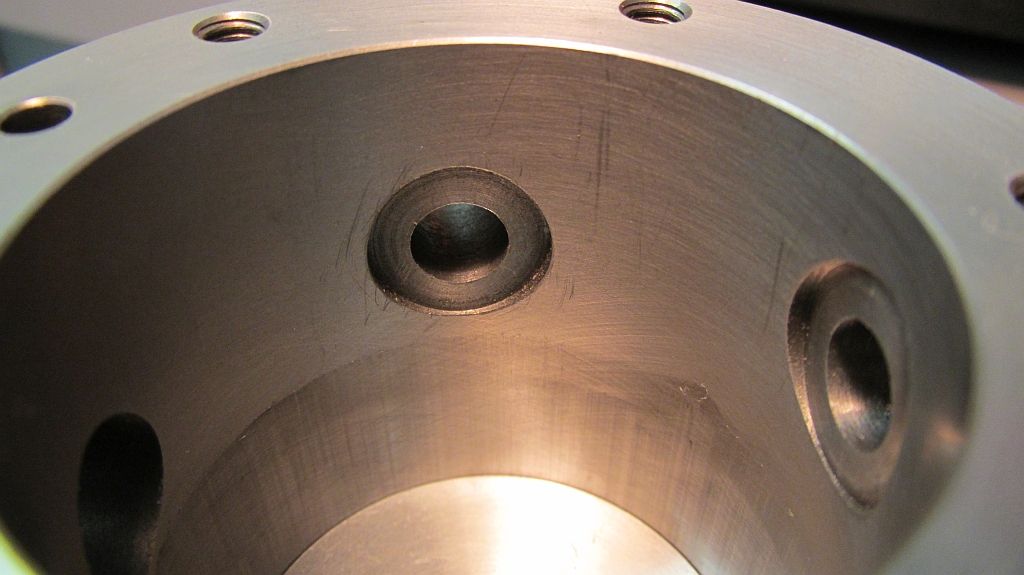

I decided to counter bore the inside of the cylinder for the mica to sit in; as far as I know this is also how the original engine was done. I modified a standard counter bore (cut off) so it would fit in the cylinder bore.
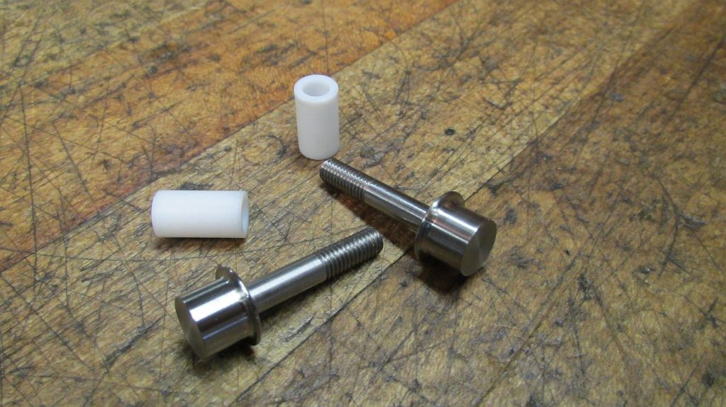

Teflon insulator bushings were turned along with the start of the feed throughs; the feed throughs were made form 303 stainless steel. 
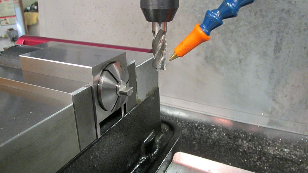

The feed through is milled half way to form the clamp area for the blade.
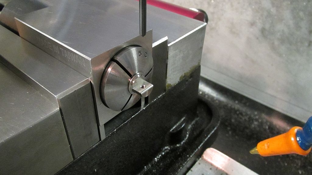

Then drilled and tapped; also the edge is given a small radius to remove a stress point from the blade.
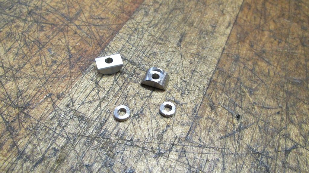

The clamp blocks are machined and counter bored to accept a boss for the clamp screw.
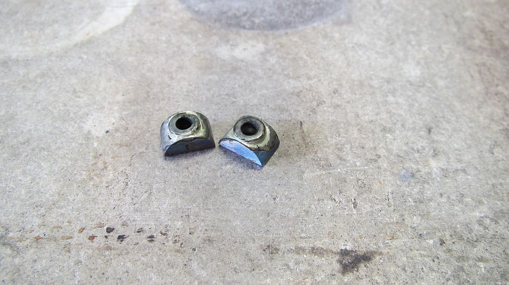

The bosses are silver soldered in place.
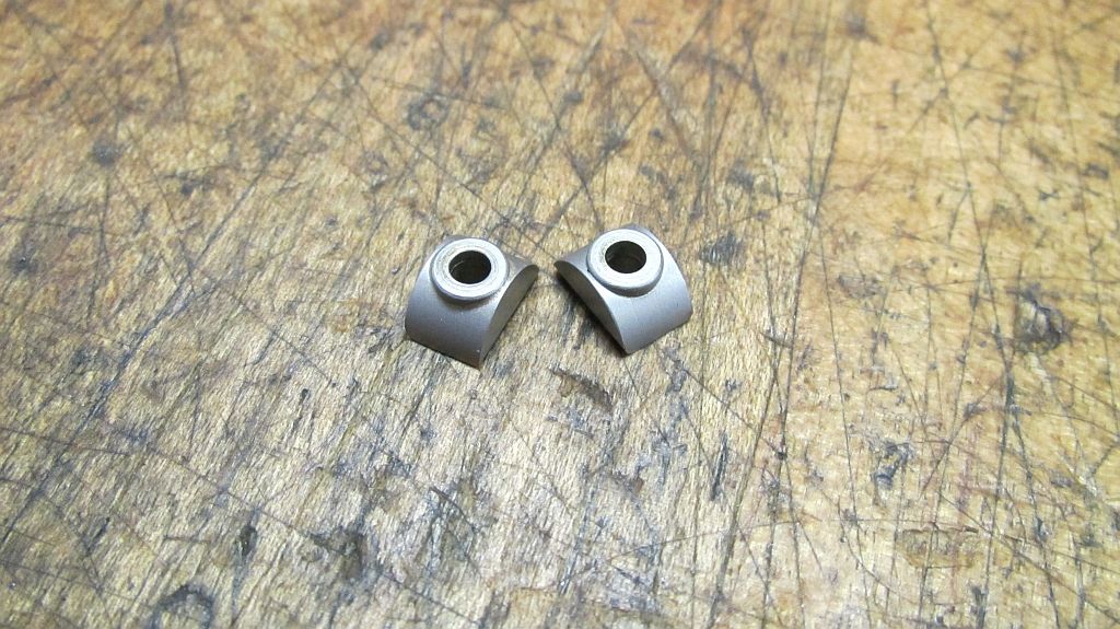

Here they are after cleaning and a trip through the blast cabinet.
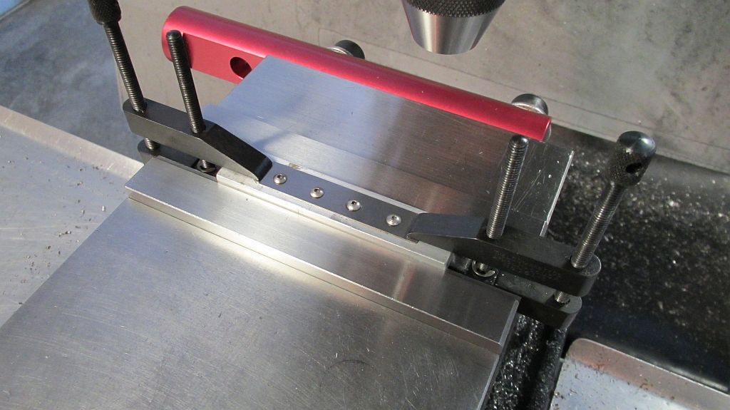

The blades are machined out of a commercial air compressor valve spring; the spring just happened to be the right thickness. The stock is screwed to a chucking piece and the clamps removed.
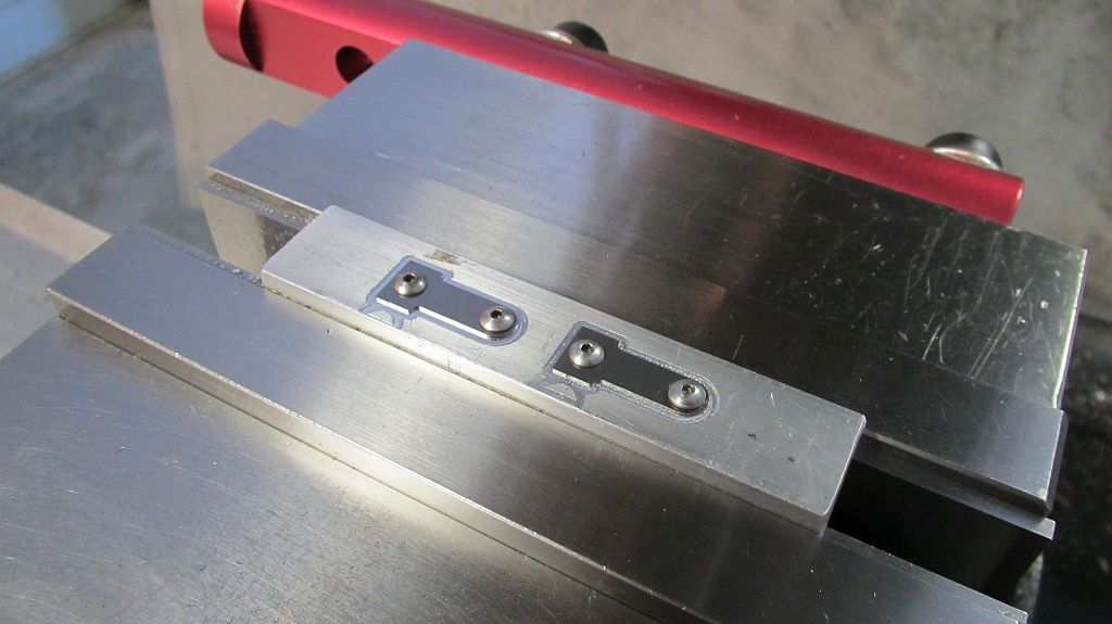

The blades are profiled using a small carbide end mill.
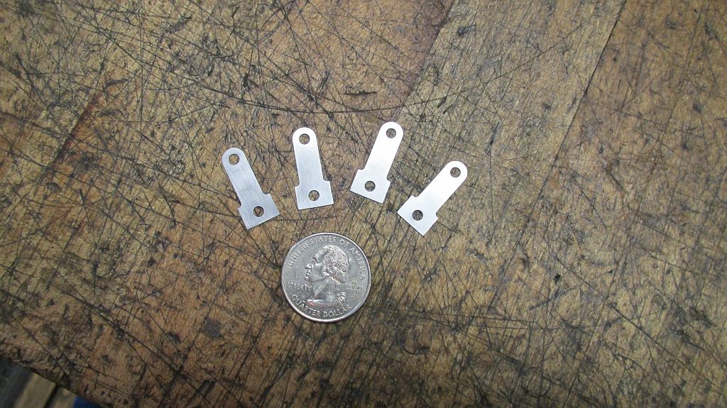

Here they are ready for the points to be installed; also made a couple of spares while I was set up and going.
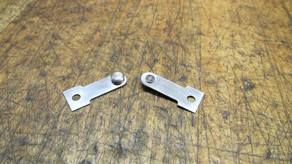

The points were machined out of meteor metal that I purchased from one of the magneto guys a number of years ago. I think that it is high in Nickel but not sure what else is in it. I plan to take a sample to work and have one of the guys in the lab check it out.

I may also try German silver point material as this is what one of the gas engine suppliers is selling for Ignitor point replacements in the full sized antique engines
The points were swagged in place after machining.
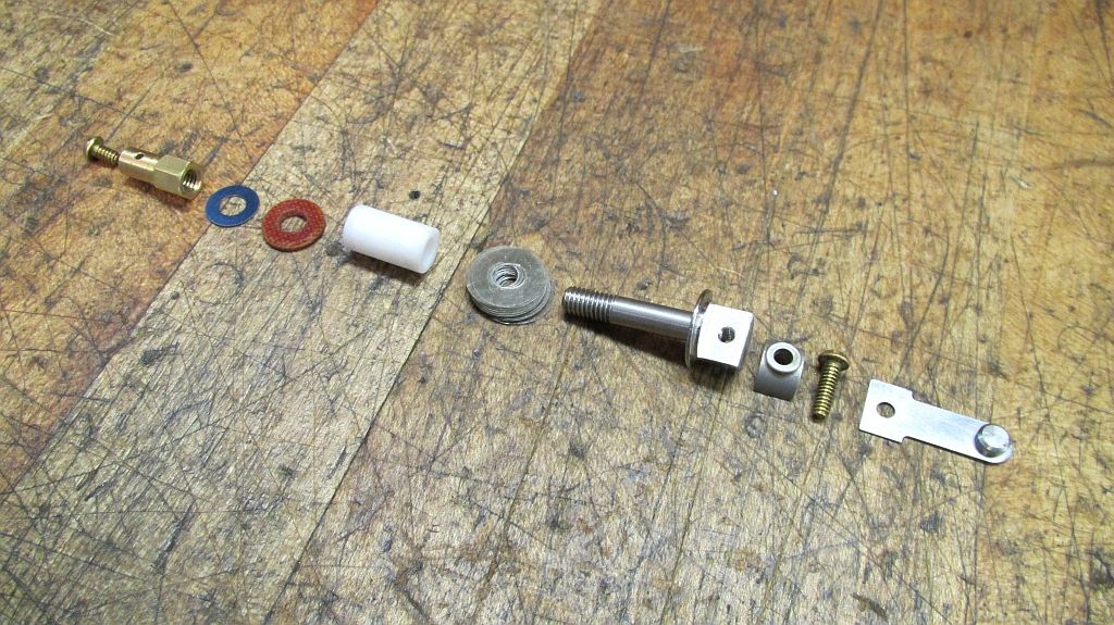

Here is the lineup of all the parts for one feed through assembly. The mica washers are added or removed to properly align the points. The outside insulator is made from linen phenolic followed by a thin washer punched from some blue spring steel and then the brass nut/ wire clamp.
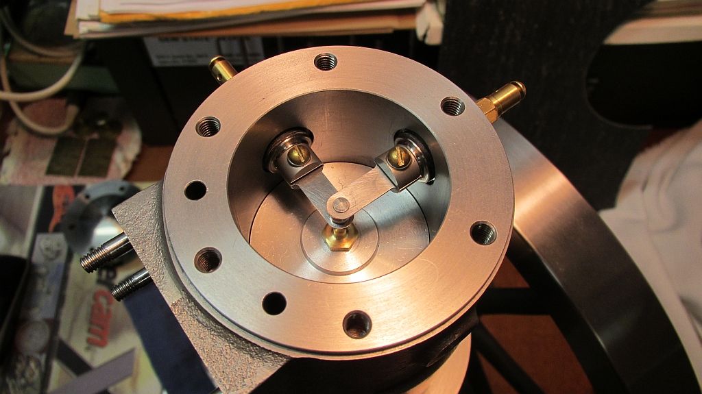

Here are all the parts installed in the cylinder; notice the brass button screwed into the top of the piston.
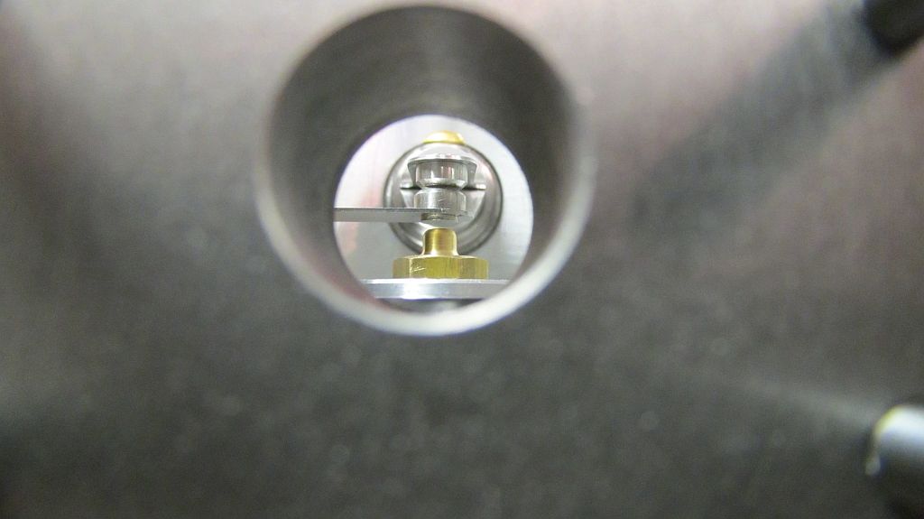

Here is a shot through the exhaust port; the button on the piston closes the points on the way up and then the point open as the piston starts back down.
Because room is tight all fine adjustments will be made using shims; either under the trip button or under the blades. I lengthened my connecting rod to increase the compression ratio so there is not enough room for the stud and jam nut that would have originally been used on the top of the piston.
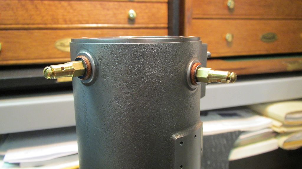

Here are a couple shots of the outside parts.
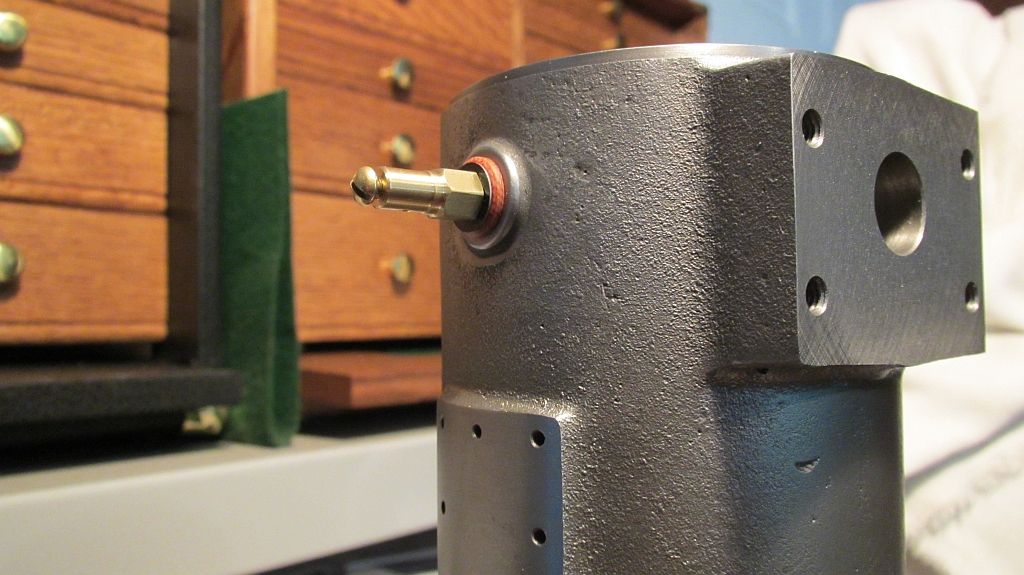

The major problem with this system is there is no spark advance; the engine will always runs in a retarded condition. It was 1890 after all and this engine represents some of the very early US engine development.


Thanks for checking in.
Dave 


Offline Don1966

  • Full Member
  • *****
  • Posts: 6818
  • Columbia, MS
Re: Pacific Vapor Engine from Morrison & Marvin Castings
« Reply #224 on: September 16, 2013, 03:34:07 AM »
Dave those beers must of helped you a lot getting the igniter setup. You have done a jam up job of it. Nice work bud.  :cheers:

Don


SimplePortal 2.3.5 © 2008-2012, SimplePortal