Author Topic: James Coombes - Not As You Know Him  (Read 5724 times)

Offline RReid

  • Full Member
  • ****
  • Posts: 1699
  • Northern California
Re: James Coombes - Not As You Know Him
« Reply #30 on: February 10, 2023, 02:19:46 AM »
Quote
...was used to cut the decorative weight reduction hole that you often see on full size engines.
Well, I haven't seen that before, but I do like it a lot.
Regards,
Ron

Offline vtsteam

  • Full Member
  • ****
  • Posts: 753
Re: James Coombes - Not As You Know Him
« Reply #31 on: February 10, 2023, 09:21:31 PM »
Beautifully done.  :ThumbsUp: :ThumbsUp: :popcorn: :popcorn: :cheers:
Steve

Offline Jasonb

  • Full Member
  • *****
  • Posts: 9489
  • Surrey, UK
Re: James Coombes - Not As You Know Him
« Reply #32 on: February 15, 2023, 04:55:38 PM »
One small job that was next to be crossed off the list was making the Acorn nuts for the top of the columns. I started with some free cutting round bar and milled to a hexagon using the 5C indexer. Then over to the lathe the shaped top was cut with the ball turner before parting off and then holding the other way up to drill and tap the nut.


I then tackled some of the valve gear starting with the levers that take the angled motion of the eccentric rod via a shaft to vertical movement that the valve requires. I actually made these links a while ago as they served to show a couple of different options for CNC machining that was being discussed in another thread at the time.

Starting with some 1/4" flat bar the holes for the three levers were spot drilled, then drilled with stub drills 0.2mm undersize and finally reamed.


The levers were then milled down to the required thickness, one at 5mm the other two at 6mm thick


I then used the witness marks from milling to line up the band saw to cut the individual parts from the bar


Over to the CNC and two holes were drilled and then manually tapped in a tooling block, this lines up the holes and sets one as datum which is easier than drilling manually and then having to locate the hole when the block is transferred to the mill.


I then ran two of the levers using an adaptive path to remove most of the material and then two contours of 0.2mm and then 0.1mm depth to finish the part this took 72seconds and as full depth cuts were used throughout the wear was spread along a reasonable length of flute. The last one I did as though the part were being cut from a larger sheet slowly ramping down to depth and then a contour to finish, this took 230seconds and almost all cutting was just with the end of the tool so wearing that short length more.

<a href="https://www.youtube.com/watch?v=FUoFZNd8ebI" target="_blank">http://www.youtube.com/watch?v=FUoFZNd8ebI</a>

Stuarts show the levers with just straight edges but I went with a dog bone shape to add a bit more character as also stop them looking so bulky


The final op was to mill slots for the vertical rods in the thicker two levers, and a thinner slot (still to be done) in the 5mm thick one for the eccentric rod


Like the levers I gave the two blocks that support the cross shaft a bit more shape and as they looked a bit chunky also reduced the thickness between the round boss and the base. These were done from a bit of rectangular bar making use of the CNC again to get good transitions between the various radii. After this photo they were sawn off the bar, the base milled flat and then drilled and tapped M2.5 for fixing studs.

« Last Edit: February 15, 2023, 04:59:47 PM by Jasonb »

Offline Jasonb

  • Full Member
  • *****
  • Posts: 9489
  • Surrey, UK
Re: James Coombes - Not As You Know Him
« Reply #33 on: February 19, 2023, 04:56:59 PM »
Working up the engine the next parts of the valve train were the two vertical lifting links, I cut and milled some 6mm wide strips from 3mm sheet and after drilling & reaming the ends set to machining them between ctrs but did not get that far on the first one :(


Changing tactics I cut two pieces of EN1A round bar and did the turning first driving with one end in the chuck and the other end supported by the tailstock. A 0.8mm radius tip was used to leave a small fillet at the ends of the taper which was turned with the cross slide set over and then all blended into a fishbelly shape.


Then over to the mill to machine flats at the ends before drilling and reaming 3mm, the waste material at the ends was sawn off and then the rods rounded over in the same way as the conrod was done earler


Rather than be stuck with Stuarts half turn of the valve rod to make adjustments I decided to put a hole right through the yoke and retain the rod with a nut top & bottom that way I can get infinite adjustment of the valve nut's position simply by rotating the rod. Here I have part turned one side then with it held in teh indexer a square has been milled and cross drilled.


This shot shows a final bit of decorative turning being done, the ends have been reduced to 3mm and threaded and I have slipped a short length of rod over the threaded spigot so that I can use the tailstock for support without the need for a Ctr hole.


And this is the bits roughly assembled


A small offcut of bronze was milled down to the overall sizes of the valve and the upper porting reduced in size all round and I also chamfered the top corner sto allow a bit easier air flow


Whilst still in this position the slot for the rod was cut and then the one for the nut opening up the initial 2.5mm wide cut until the nut material was a free but snug fit in the slot


Finally a 2mm cutter used to form the cavity in it's underside


Not much to say about the nut except it was milled down to 6mm x 3mm section, milled to length and then drilled & tapped M2.5, guiding the tap to ensure the tapped hole was true and vertical.


Offline John Roberts

  • Full Member
  • ****
  • Posts: 117
Re: James Coombes - Not As You Know Him
« Reply #34 on: February 20, 2023, 08:51:04 PM »
What is your conclusion regarding adaptive tool paths v contour? I have only used the later. I  can see the logic in wearing out the cutter along the flutes rather  than the bottom. I would have to re learn what width of cut to go for  specially on steel.
 

Offline Jasonb

  • Full Member
  • *****
  • Posts: 9489
  • Surrey, UK
Re: James Coombes - Not As You Know Him
« Reply #35 on: February 21, 2023, 08:01:56 AM »
I've put a reply into a new thread so hopefully a few others with CNC will also comment on what they tend to use

https://www.modelenginemaker.com/index.php/topic,11301.msg263253.html#msg263253

Offline Jasonb

  • Full Member
  • *****
  • Posts: 9489
  • Surrey, UK
Re: James Coombes - Not As You Know Him
« Reply #36 on: February 24, 2023, 07:23:40 PM »
Working up the engine while waiting for the Cylinder casting the next part to make is the cylinder end cover which also serves as a mount for the two cross head guides. I wanted to do this from Cast iron and the most economical way was to start with a slice of iron bar


Held in the soft jaws it was cleaned up on the OD, faced and then a 25mm spigot turned to locate in the end of the cylinder, the piston rod hole was then drilled with a 4.8mm stub drill before reaming 5mm


Held the other way round again in the soft jaws it was faced to length before thinning down most of it to 4mm to leave a central boss which was counterbored 8mm dia for the gland and also a shallow recess turned around it for a bit of added interest and somewhere to stop the paint.


After roughly squaring up so it could easily be held in the vice jaws the ctr was located and various holes drilled - four for the guides, eight for the cylinder studs and 3 for the gland studs.


Finally using a couple of drill bit sin suitable holes the final 50mm square was machined and then a corner radius cutter used to add a small decorative moulding around the edge.


A start was then made on the cross head guides two pieces of overthickness (8mm) bar were milled to 12mm width, 6mm holes drilled each end so they could be held on a mandrel and rounded over using the rotary table. Here I and just roughing out the slots with a 6mm cutter to reduce some of the bulk so they don't take so long to bring up to soldering temperature.


The webs were done from 3mm sheet, rough sawn they were then clamped to the CNC and the oblong slots machined. I then used a couple of top hat bushes to hold the parts to a jig plate through this slot while the outer profile was cut. I also ran a chamfer mill around what will be the outer edges to make subsequent rounding over easier. I also designed the bottom of the guides with two feet rather than a solid base as the Stuart design looks a bit bulky in this area.


A couple of lengths of 8mm square were slotted to locate onto the webs and two round bosses cut for the tie bar at the top and that is all the parts ready to solder.


Here is one that has been soldered, I used a couple of short lengths of the slotted 8mm sq to hold the other end of the web at the correct central height


After a dip in the pickle I set the assembly up in the mill vice and took equal amounts off each side to bring the rough 8mm thickness down to the required 6mm. Then plunged the ends of the slot to 8mm dia with a 3-flute milling cutter


A 6mm cutter was then used to open up the slot to 8mm width and also machine the feet to the correct height relative to the slot. Top boss hole was also drilled relative to the slot.


Once out of the middle of the foot strip was sawn away and the two feet milled to length ready for a quick trial fit


Offline uuu

  • Full Member
  • ****
  • Posts: 102
Re: James Coombes - Not As You Know Him
« Reply #37 on: February 24, 2023, 08:13:00 PM »
It's so elegant!  It will  be fabulous.

Wilf

Offline Admiral_dk

  • Full Member
  • *****
  • Posts: 3777
  • Søften - Denmark
Re: James Coombes - Not As You Know Him
« Reply #38 on: February 24, 2023, 08:42:22 PM »
That looks really good Jason  :praise2:

Interesting build up  :ThumbsUp:

Per      :cheers:

Offline steam guy willy

  • Full Member
  • *****
  • Posts: 3247
Re: James Coombes - Not As You Know Him
« Reply #39 on: February 24, 2023, 10:17:31 PM »
Hi Jason , still following along and was wondering how the eccentric is attached to the shaft ??....good work here
Willy....

Hi, ok have read the text properly and see that there is a grub screw !!!
« Last Edit: February 24, 2023, 10:23:25 PM by steam guy willy »

Offline Dave Otto

  • Full Member
  • *****
  • Posts: 4707
  • Boise, Idaho USA
    • Photo Bucket
Re: James Coombes - Not As You Know Him
« Reply #40 on: February 25, 2023, 12:35:47 AM »
Nice fabrication I enjoyed seeing your process on this one.
That is getting to be quite an assembly!

Dave

Offline Jasonb

  • Full Member
  • *****
  • Posts: 9489
  • Surrey, UK
Re: James Coombes - Not As You Know Him
« Reply #41 on: February 27, 2023, 07:01:04 PM »
Thanks for the comments and following along.

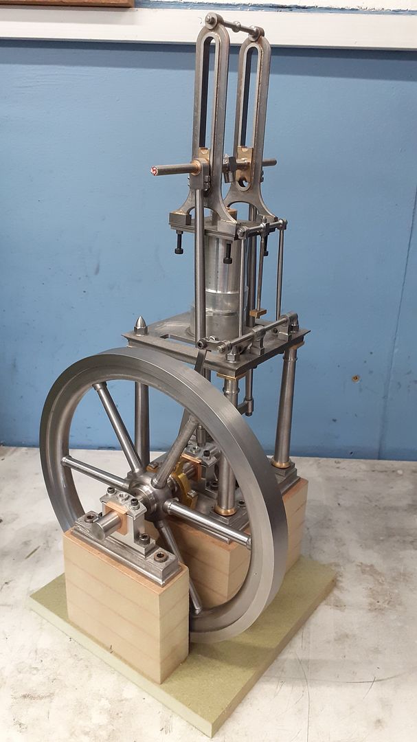
I had been debating for a while whether to use the usual 7" Stuart flywheel casting or to go with something a bit different. Having already machined five of these the prospect of another one did not really offer a challenge and with the casting costing just under £50GBP (Edit £60)  once tax and delivery had been added decided me to see what I could knock up. I like the look of the near 10" flywheel used on a couple of the Clarkson engines and a similar style is used on Anthony Mount's Waller Table Engine so I decided to do one like that at 200mm diameter.

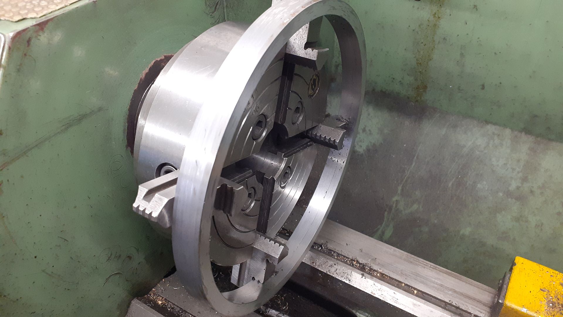
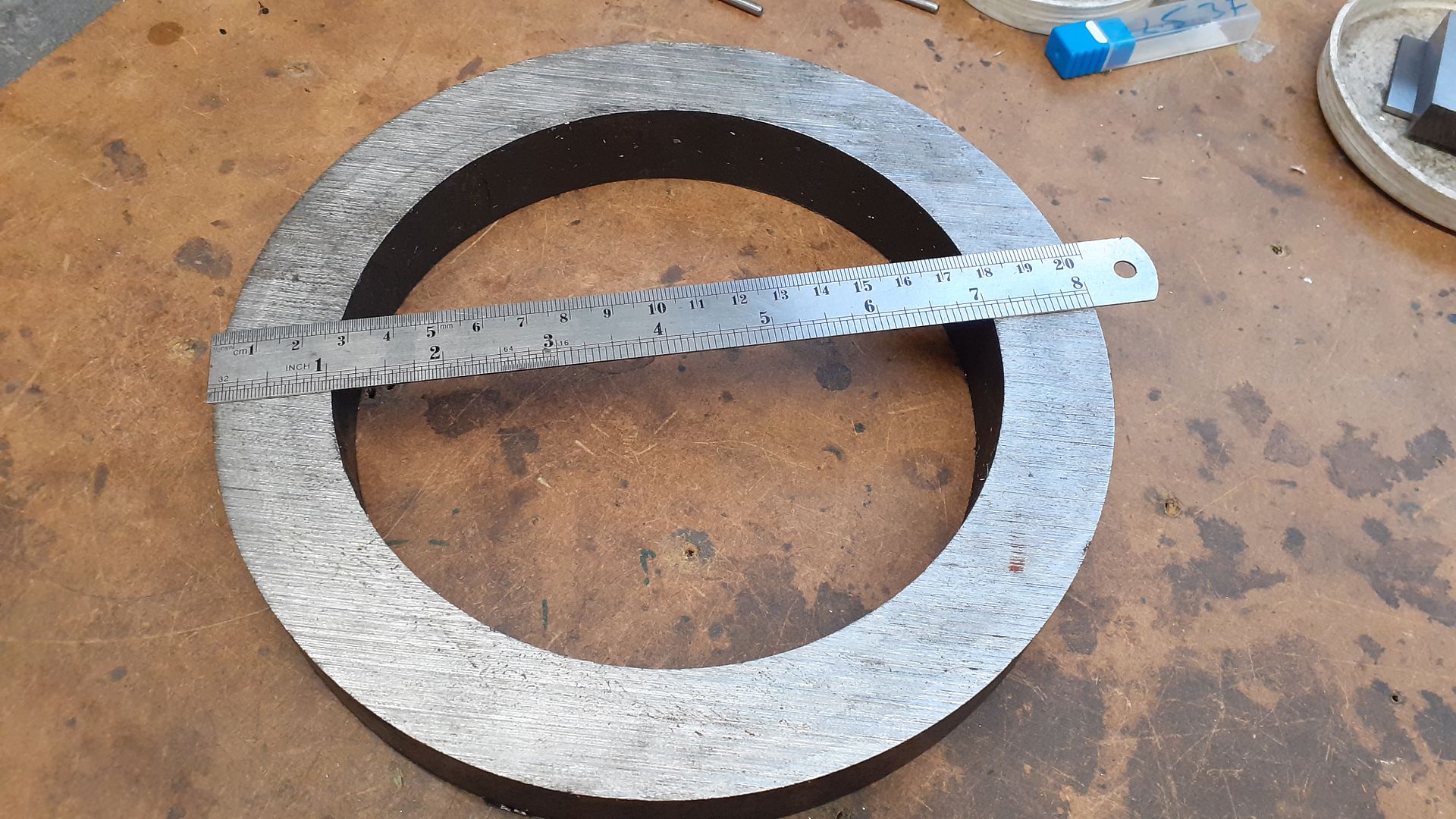
I originally just ordered some 203mm x 12.7mm wall (8" x 1/2") tube for the rim but the wall was actually a bit thinner and by the time I had cleaned up the hot rolled surfaces things would have looked a bit skinny so I decided to use this as an outer rim that could be slipped over an inner one which had the added advantage of hiding the holes for the spokes.

I made a start by cleaning up the OD, facing the edge and boring out the inside on which I left a small 0.3mm step half way in so that I could locate the inner rim against that.


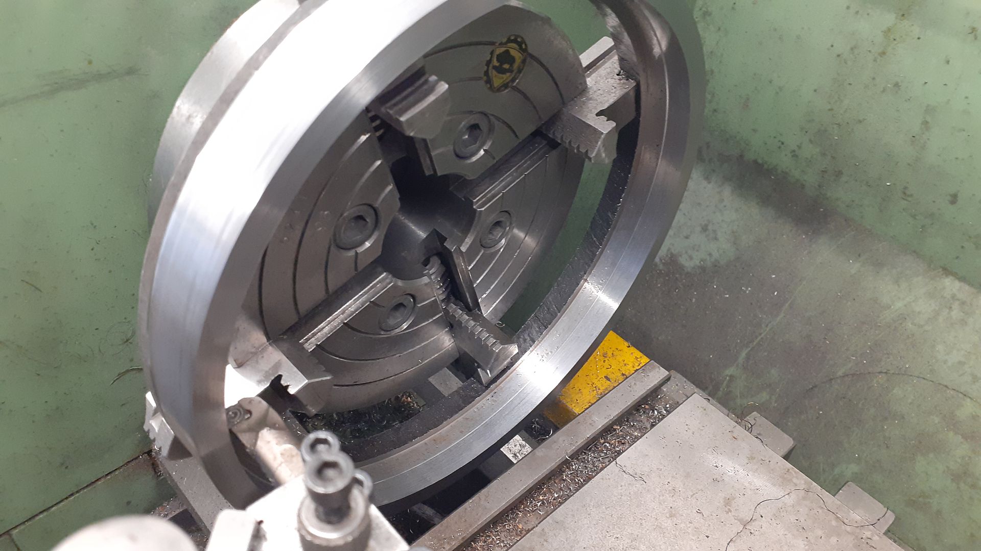
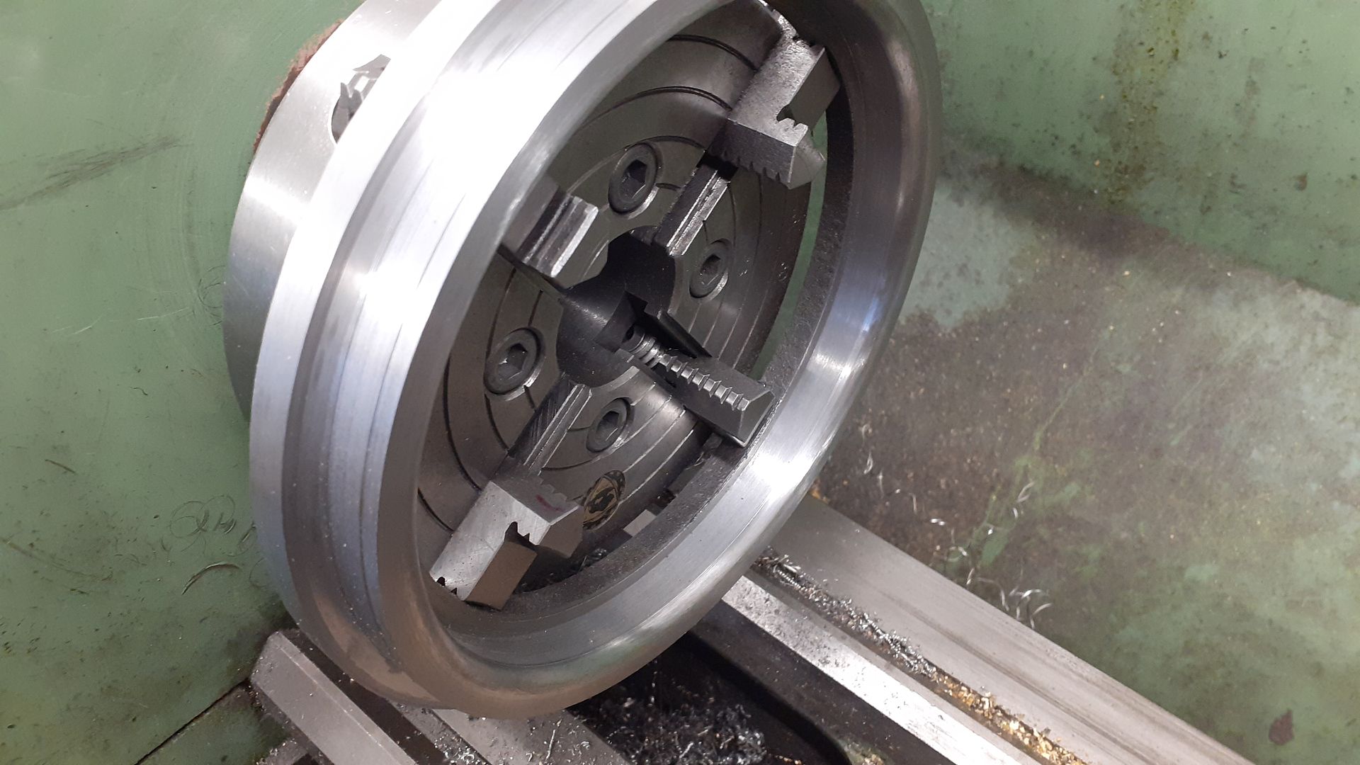
I then reversed the ring in the chuck and faced it back to a little over finished width


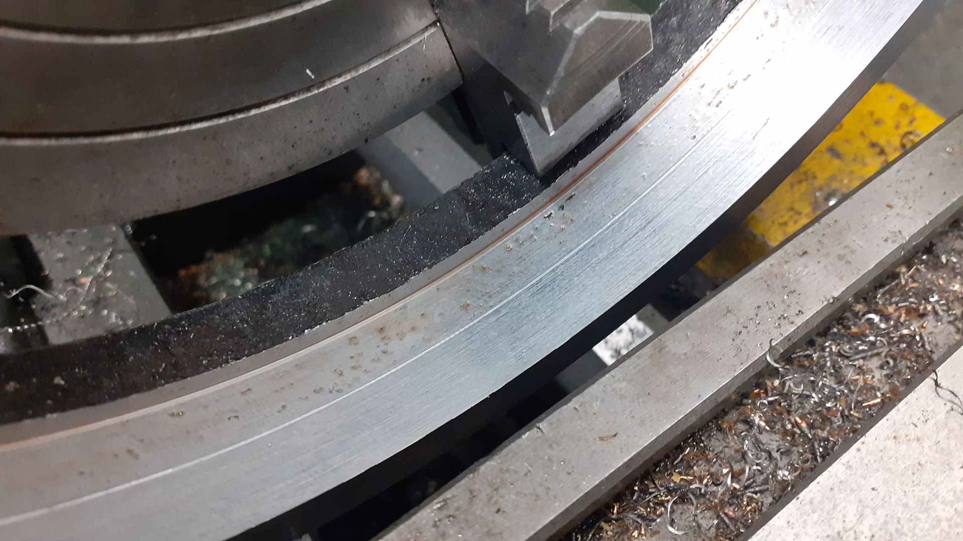
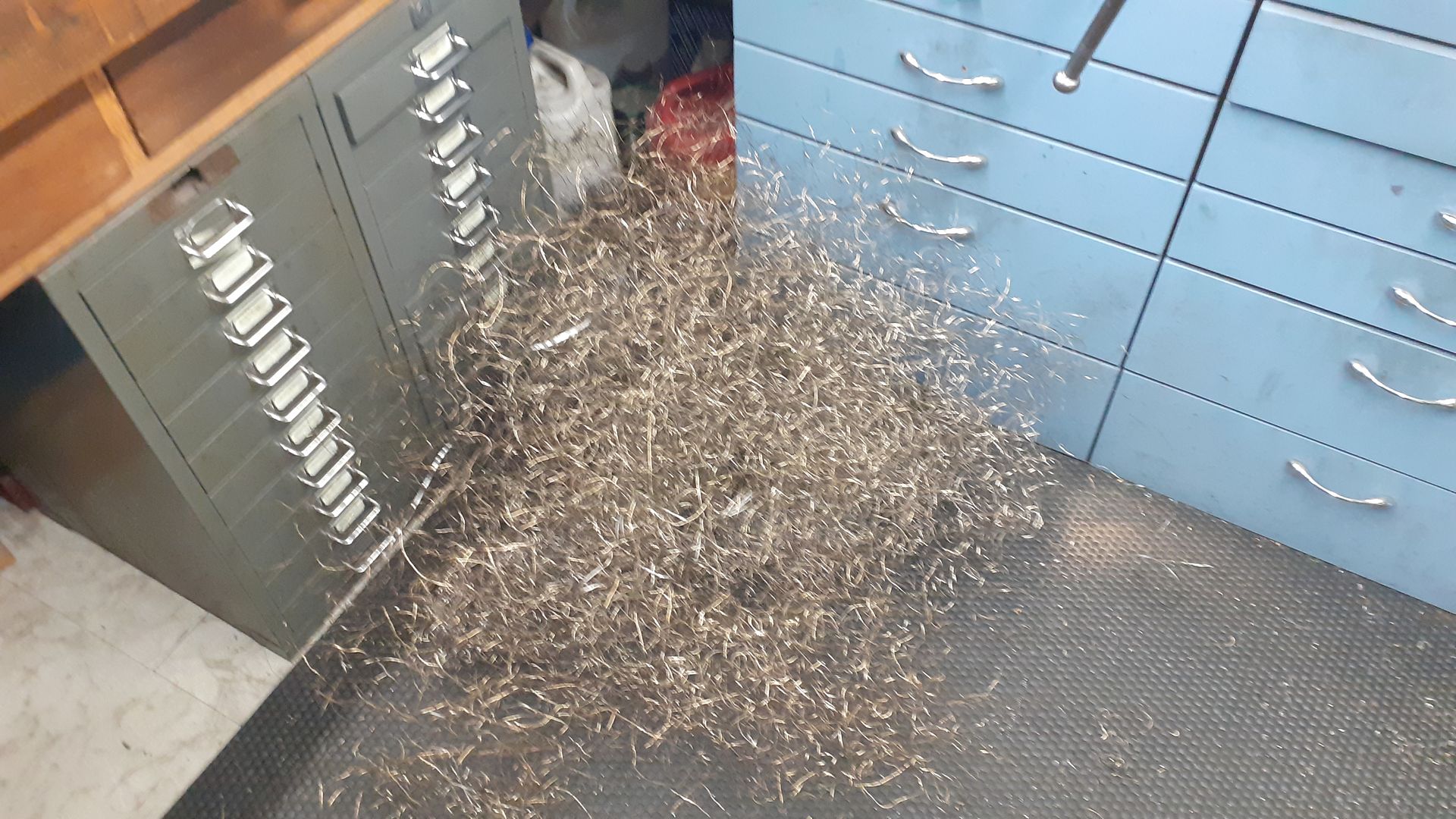
Not the nicest steel to machine, a CCGT insert seemed to work best but did not break the chips so ended up with long swarf.


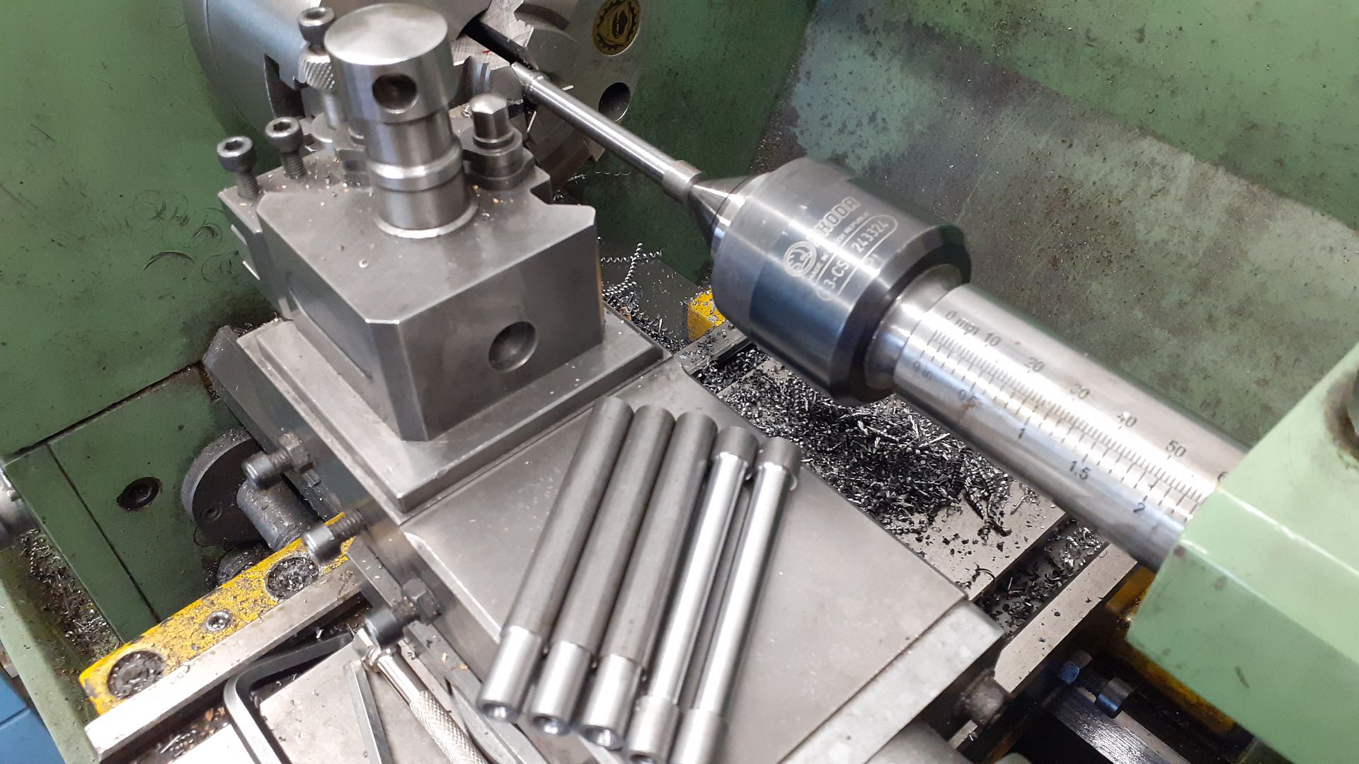
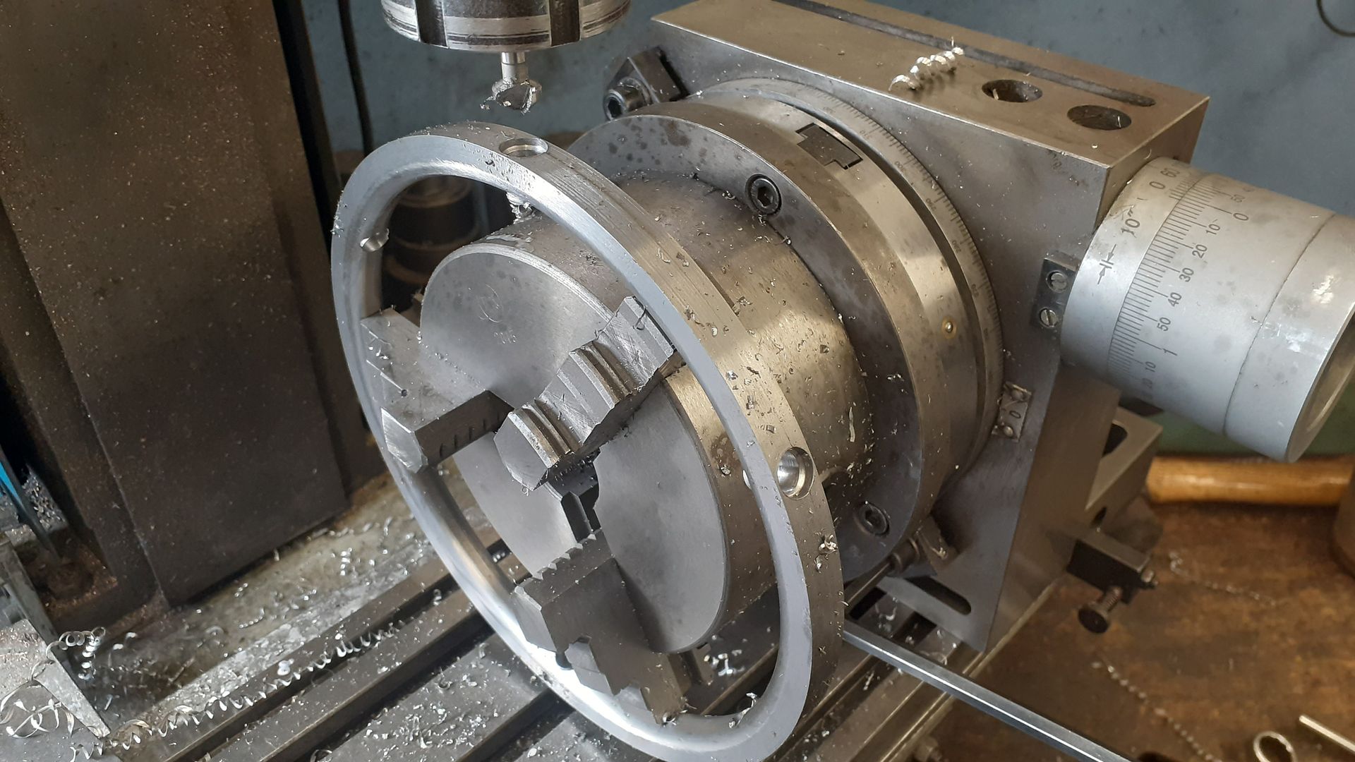
Having a change from the big stuff I did the spokes next, six pieces of 10mm steel were sawn off, faced to the same length and after heavily ctr drilling both ends one was tapped M4m the other M5, the deep drilling still offering a surface for the ctr to locate in.  A short length of each was reduced to 9mm diameter and then using tailstock support the central section was taper turned from 8mm to 7mm leaving "bosses" at the ends of 10mm and 9mm. Here I am half way through the taper turning.


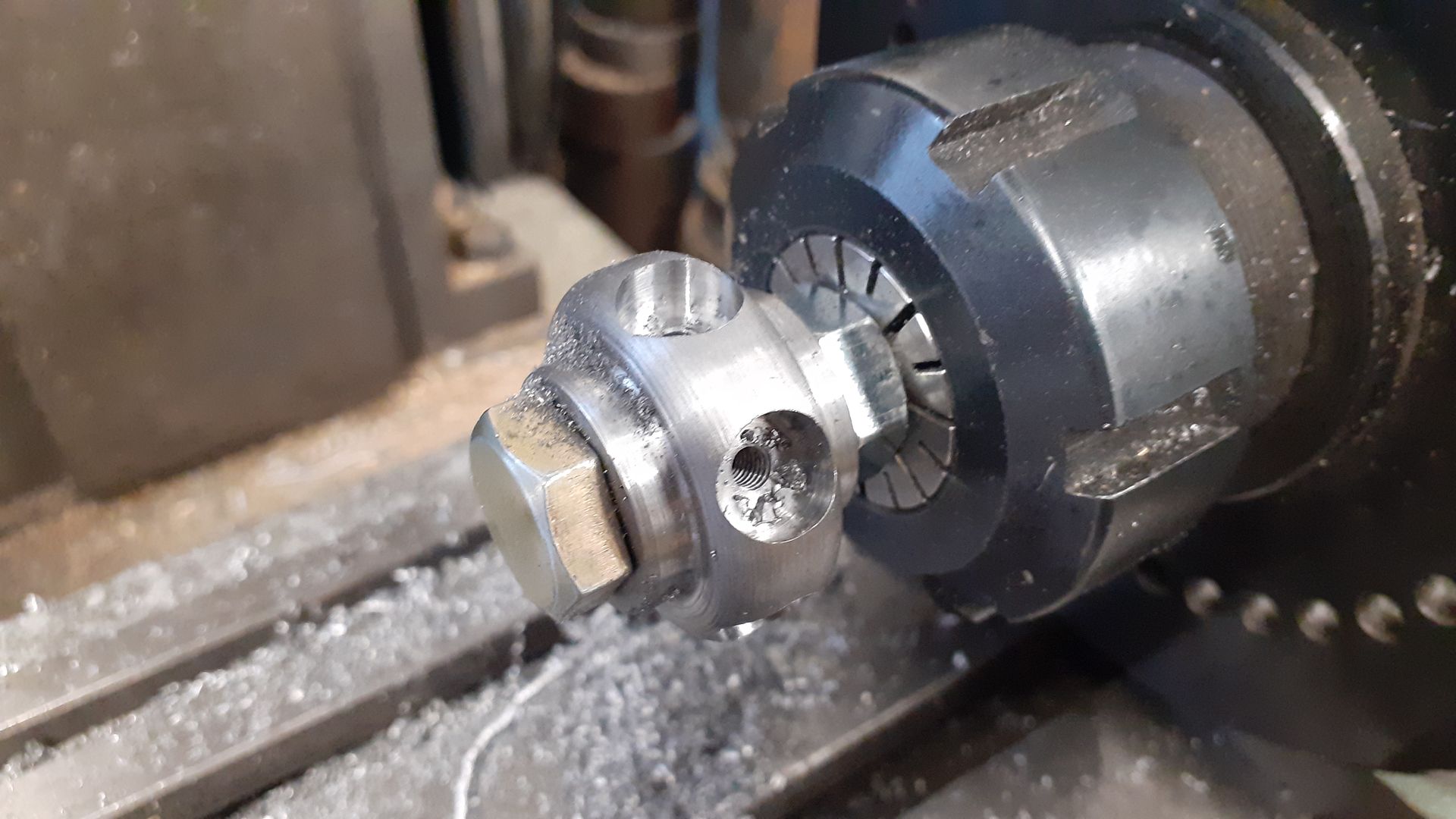
The bub was bored undersize and then turned to a pleasing profile before being transferred to the spin indexer to have 10mm dia pockets plunge milled for the thick ends of the spokes and also drilled & tapped M4


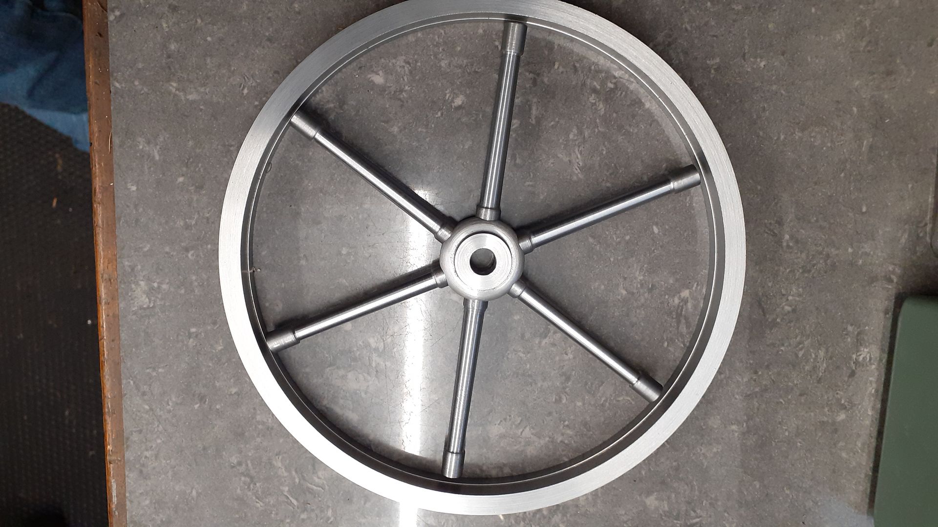
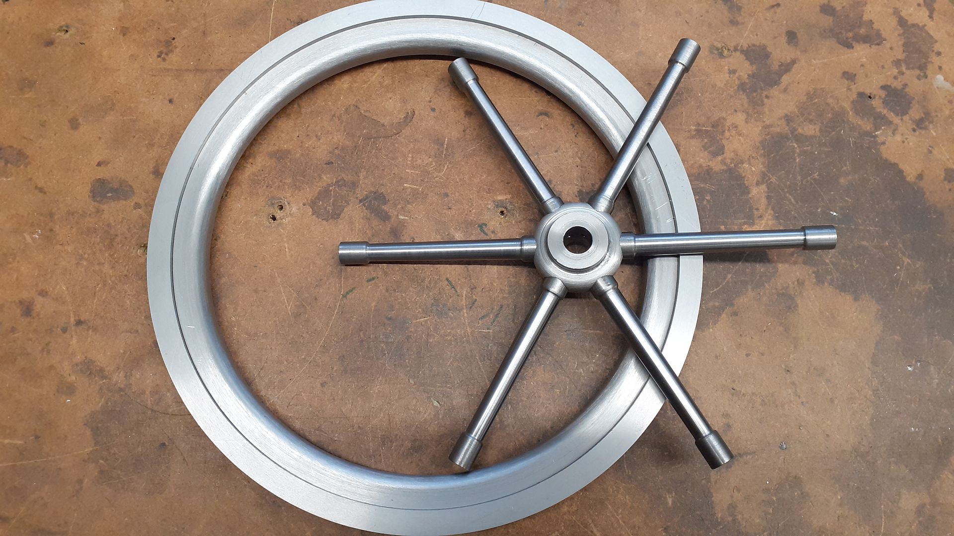
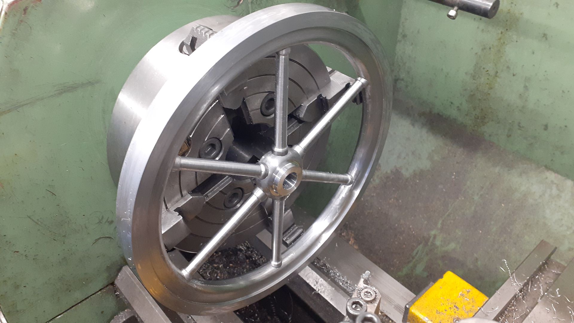
Using some short lengths of M4 threaded rod the spokes could then be screwed into the hub and drawn into their pockets, quick assembly to see how things are looking


For the inner rim I used a 25mm long slice of 203 x 25 tube which meant even more swarf as that was the only size that would give what I wanted.


This had the stepped OD turned, bored out to size and faced, not easy to see but I have also rounded over the inner corner to a 5mm radius


To stop the swarf pile getting too large I decided to part off the bit I wanted but to save having the ring rolling across the workshop stopped the parting tool 0.5mm short of break through and finished with a hack saw. What is left will make another flywheel. The rough side was then faced and the corner rounded over


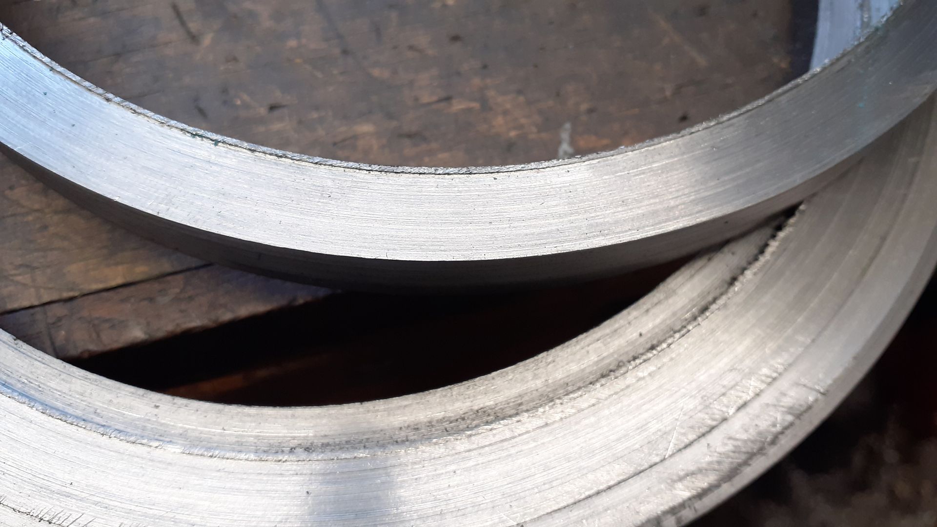
Test fit of the two part rim, just needed  alight tap with a nylon hammer so will go together with loctite.


I then drilled six equally spaced 9mm holes around the inner rim to locate the smaller ends of the spokes and deeply countersunk then so I could use M5 socket CSK screws to "true" the wheel much like you do on a bike wheel.


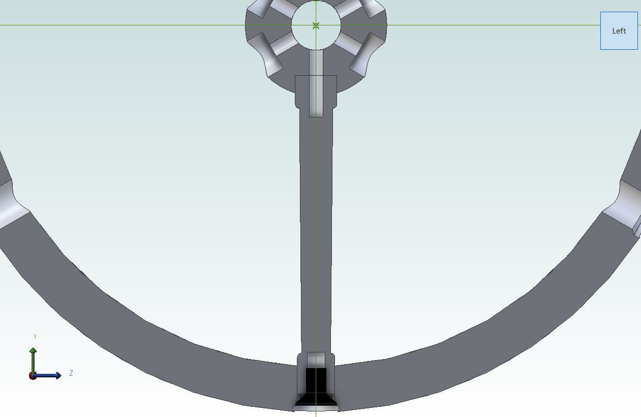
In my excitement of putting it all together I forgot to take a photo but the setup was to hold the inner rim in the lathe chuck, poke the spokes through the holes from the inside out and then bring the hub into position by holding it with teh tailstock chuck. I could then apply a bit of JBWeld to the spoke ends,, screw them into the hub and then add the CSK screws to pull it all together. A section through the assembly may help to show that.


After Loctiting on the outer rim I once again set it up in on the lathe to skim the outer rim and finish bore the hub so all will run nice and true. After test running some fillets of bondo will be added around each boss to get the "cast look" I also opted for a taper gib key rather than Stuarts grub screw.


Trial fit


« Last Edit: February 28, 2023, 07:57:21 AM by Jasonb »

Offline crueby

  • Full Member
  • *****
  • Posts: 18681
  • Rochester NY
Re: James Coombes - Not As You Know Him
« Reply #42 on: February 27, 2023, 07:29:15 PM »
Nicely done, that looks in great proportion!   :popcorn:

Online Kim

  • Global Moderator
  • Full Member
  • *****
  • Posts: 7925
  • Portland, Oregon, USA
Re: James Coombes - Not As You Know Him
« Reply #43 on: February 27, 2023, 10:11:08 PM »
Lot of work to get that nice looking fly wheel, Jason!   :popcorn:

Was it still cheaper than the casting?  Or just cheaper because you had all the parts already.  (Which is still cheaper, isn't it?  :Lol:)

Kim

Offline vtsteam

  • Full Member
  • ****
  • Posts: 753
Re: James Coombes - Not As You Know Him
« Reply #44 on: February 28, 2023, 12:05:18 AM »
I think it's elegant, and I like the columnar taper look of the spokes. Looks just right with the rest of the engine.  :ThumbsUp: :ThumbsUp: :popcorn: :popcorn: :cheers:
Steve


SimplePortal 2.3.5 © 2008-2012, SimplePortal