Some good progress on the steam hammer cylinder. As mentioned yesterday, I needed to trim off the side of the lower block to form the flat for the backing plate. Used a dial indicator to set the existing cylinder flat level to the mill, turning the rotary table slightly till it read the same across the flat face.

Then trimmed off the lower block, on the left in the picture, till it was flush with the flat on the cylinder
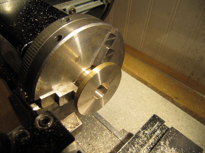
Unbolted the cylinder and took the faceplate and block over to the lathe, where I trimmed off the bottom flange (on the left of center in the picture) to size, and then parted it off.
Gripped the part by the outer end and trimmed off the parted face, and also counterbored the hole out to 3/4" most of the way through to take the piston rod gland parts.
In the plans, they show making the holes in both the gland holder and the gland as round-ended/flat sided holes to keep the piston rod from turning as it is used. But, no indication of how to do that operation, and I've seen numerous ways to do it in other build threads. So, here is the way I picked: make two parts, a thin plate and the gland plate, both shaped on one end to that odd shaped hole, done on the mill with the rotary table and a tiny end mill. Then, the plate goes into the counterbored hole, then packing material (possibly some Viton sheet cut to the shape of the hole), then the gland to hold the packing tight.
I started by turning two pieces of bearing bronze to size for the plate and the gland. The width between the straight walls is 7/16, so the center of each was bored to that size. I used the tip of the boring bar to also cut a shallow recess at 1/2" diameter on the outside edge of each to act as a milling guide. The piston rod is 1/2" diameter with the flats milled into the sides.
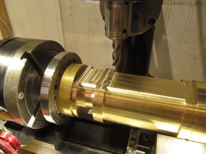
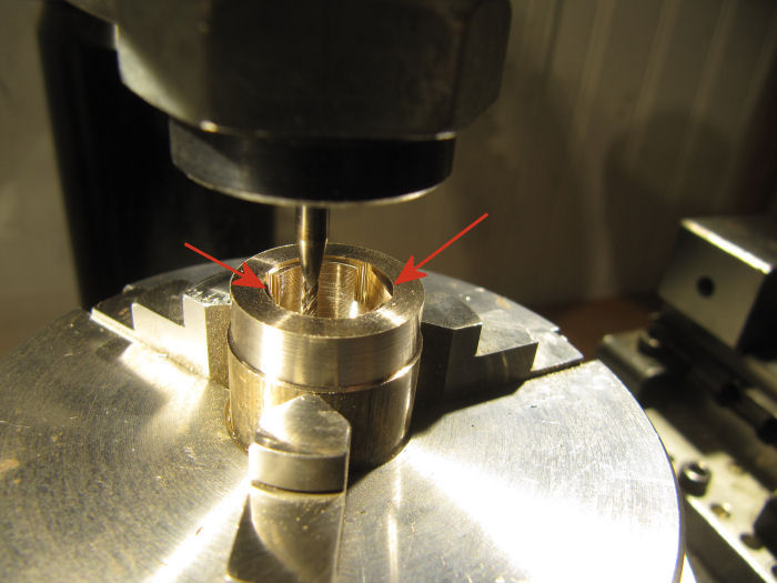
Then, moved the chuck over to the mill, on the rotary table, and locked it down at 0 degrees. With a 1/16" end mill cutter in the collet, moved the cutter over to the center of one side of the hole till it just touched, and moved the mill table in and out to cut straight lines till they touched the 1/2" recess. Faces cut are shown by the red arrows.
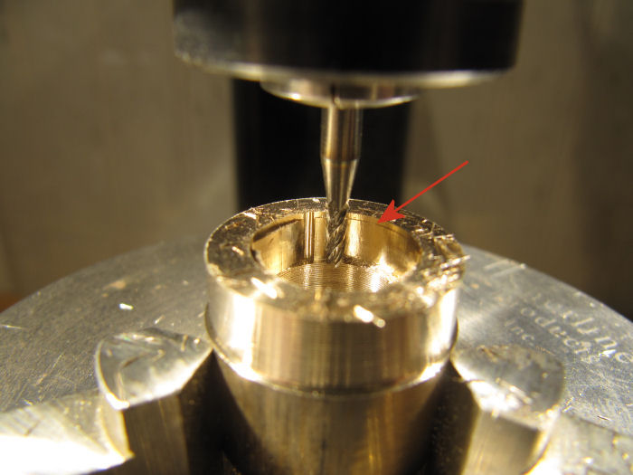
Unlocked the rotary table, and milled the arcs between the flats till they just reaced the 1/2" guide edges, staying between the two flat faces. The cut shown by the red arrow is almost to the guide arc, you can still just see a line where it steps down.
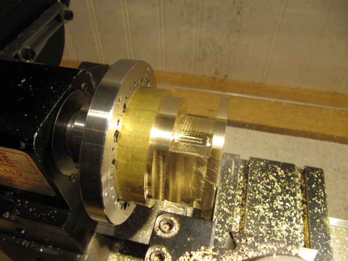
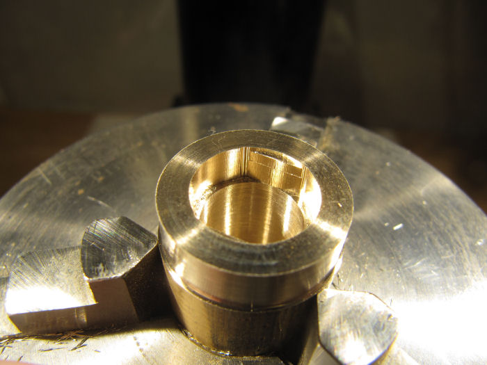
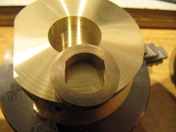
Another couple light passes to sneak up on that edge, and then did the same cuts on the arc on the other side. Here is the result - you can see the arcs at either end and the flats in the middle.
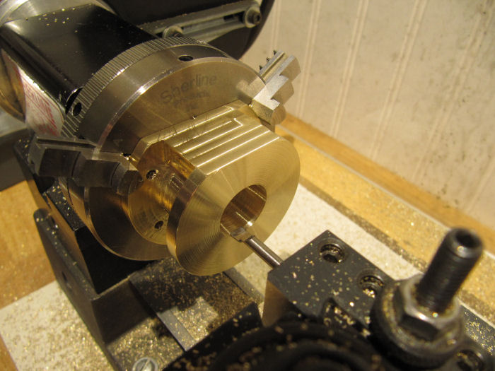
Then did the same on the hole in the gland piece. Now, that tiny end mill is not very long, so I couldn't cut that deep into the bearing. So, the thin plate was parted off, and then the gland was counterbored to 1/2" from the back side, went in just till I met the oblong hole that was cut on the mill.
Here is the thin plate, shown on the bottom block, which has the 3/4" hole most of the way through.
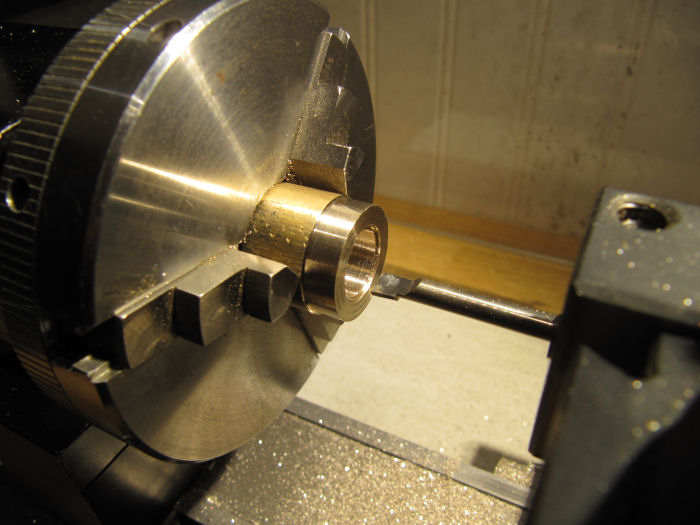
And here the plate has been pushed into the hole:

Now, I COULD have made that plate as part of the larger piece, but I wasn't sure if it would work, and didn't want to risk ruining the whole block, so this is fine. The plate is just pushed into the hole - the gland cap with its matching oblong hole will do the work of keeping the piston rod aligned, its mounting bolts will keep it from turning. Next time will start on drilling/tapping the block and cap for the mounting holes, and will show the whole assembly then.


