Author Topic: Upshur Horizontal Farm Engine - Mike's Version  (Read 8509 times)

Offline mikehinz

  • Full Member
  • ****
  • Posts: 355
Re: Upshur Horizontal Farm Engine - Mike's Version
« Reply #60 on: November 14, 2021, 08:17:21 PM »
To everyone that's taken a look at the build so far and made comments:  I really, really appreciate it!  It make all the work worthwhile! 

I've taken a few days away from the shop but then jumped back in and made the hit-n-miss parts so I'll start documenting that now in the next post.

Again, thanks to all for your extremely positive comments!

Mike
MIke
Wichita, KS, USA

Offline mikehinz

  • Full Member
  • ****
  • Posts: 355
Re: Upshur Horizontal Farm Engine - Mike's Version
« Reply #61 on: November 14, 2021, 08:52:14 PM »
So when we left off this engine's build process, I'd managed to get the engine running sans hit-n-miss (hnm) mechanism.  One of the main reasons that I wanted to build this engine was to learn how hnm mechanisms work and how to build them.  So, I'll document building the individual bits in this post.  I may break up the post if this gets too long.

First up, I wound some lengths of spring for the hnm mechanism.  That's .014" music wire wound on a mandrel in the lathe set to 72 tpi and running as slow as my lathe would go, about 90 rpm.  I've shown my guide setup earlier so I would repeat that here.  The shorter spring was about 6' of wire and the longer one was about 8' of wire.


Here are the brass hnm weights made from some .25" brass bar stock.  Just basic turning ops in the lathe so I didn't bother to show that.  I made a reduced 'head and neck' area to be able to easily install the springs and so that they would stay in place once installed. 


Here's a couple of 2-56 studs just cut from a piece of threaded rod I had on hand.  I just used a bench grinder to slightly round the ends so that the threads would start.


And here are the weights and studs fitted together just to make sure that they'd go together.


Next are the hnm arms.  I started  by bringing a block of steel to the largest outside dimensions, locating the edges and then drilling the holes for the pivot and weight attachment point fairly deep into the block as shown.


Next I turned the block as shown and using a 1/2" end mill created the features for the arms.  This was just a couple of passes down the middle and making one side a bit shorter for the arms.


And here you can see my general approach with the in-progress block on top of the drawing.


And finally we see the arms emerging!  One of my favorite operations, using a slitting saw!  I think that was a .035" saw.  I just located the top of the part to the top of the blade and then lowered it by the width of the arm and made the cut 2x times.


The arms finished against the print, except for rounding the ends of the bits that engage the hnm spool.  I do that in a bit on the belt sander. 


And here's the general arrangement of how the hnm parts will go together.  I made the spool earlier in the build thread and it's different than Upshur's original design.  As you can see 1/2 the spool engages the lever and the other 1/2 engages the arms.


I'm going to stop here with this post and continue in another one, just to keep the length of each post reasonable. 

Up next will be the carrier assembly which turned out to be a bit tricky for me.

Enjoy!

Mike

MIke
Wichita, KS, USA

Offline propforward

  • Full Member
  • ****
  • Posts: 1656
  • MN, USA
Re: Upshur Horizontal Farm Engine - Mike's Version
« Reply #62 on: November 14, 2021, 09:13:08 PM »
Very nice Mike - for some reason I particularly like the use of a 20p for size reference in the pictures!
Stuart

Forging ahead regardless.

Offline mikehinz

  • Full Member
  • ****
  • Posts: 355
Re: Upshur Horizontal Farm Engine - Mike's Version
« Reply #63 on: November 14, 2021, 09:19:13 PM »
Very nice Mike - for some reason I particularly like the use of a 20p for size reference in the pictures!

Back before I retired, my business partner was Scottish.  I send him photos every once in awhile and have to give him some familiar reference, hence the 20P coin!  And I do like the looks of it also!

Mike
MIke
Wichita, KS, USA

Offline mikehinz

  • Full Member
  • ****
  • Posts: 355
Re: Upshur Horizontal Farm Engine - Mike's Version
« Reply #64 on: November 14, 2021, 11:45:07 PM »
Ok, we're down to the last part for the hnm mechanism, the carrier.  It's a complex bit and it took me some time to figure out the best approach for it. 

I started on the lathe and turned out what is essentially a disk that has the correct ID, OD and thickness for the finished part.  Nothing too complex so far, so here's the resulting bit on the print.


I decided that the only way to do this part was to make a fixture as seen in the pix.  I squared up a piece of 5/16 flat AL stock and made the sides exactly 2.00" and then bored a locating recess and tapped the center 10-32.  You can also see a small locating pin that fits the fixture and the carrier so that the carrier can be exactly located on the fixture.  I also make a small hold down bar, not yet shown in the pix.


And here's the first op in the mill.  You can now see the hold down bar that secures the carrier to the fixture plate and allows each side to be milled down to the .063" thickness called out.  I started by locating the center for the fixture in x and y so I'd end up the correct dimension in  the middle.


After milling the sides, I drilled 6 holes thru the carrier with clearance size for 2-56.  Then I drilled and tapped the same holes in the fixture plate 2-56, which is shown in the pix.


Once those holes were drilled and tapped, I could secure the carrier to the fixture and remove the hold down bar and centering plug so that I could mill the center bit away.  Shown is the milling operation using a 3/32" end mill spinning about as fast as the Bridgeport can go.  I took it slow and easy and used my MQL system to make sure the chips were cleared and the cutter and work was well lubricated.  The nozzle for the MQL is on the left of the pix.


Here's where you can see why I used a square fixture for this part.  Now i turned the fixture in the mill vise and drilled thru tapping size and then tapped 2-56 on one side and the other side was opened up to clearance for 2-56.


And here's the finished carrier on the print.  Note that i changed it up a bit from Upshur's original design.  I left just a bit of material so that the 2 halves of the carrier remained together.  My thinking is that this would assure easier alignment when installed on the flywheel.


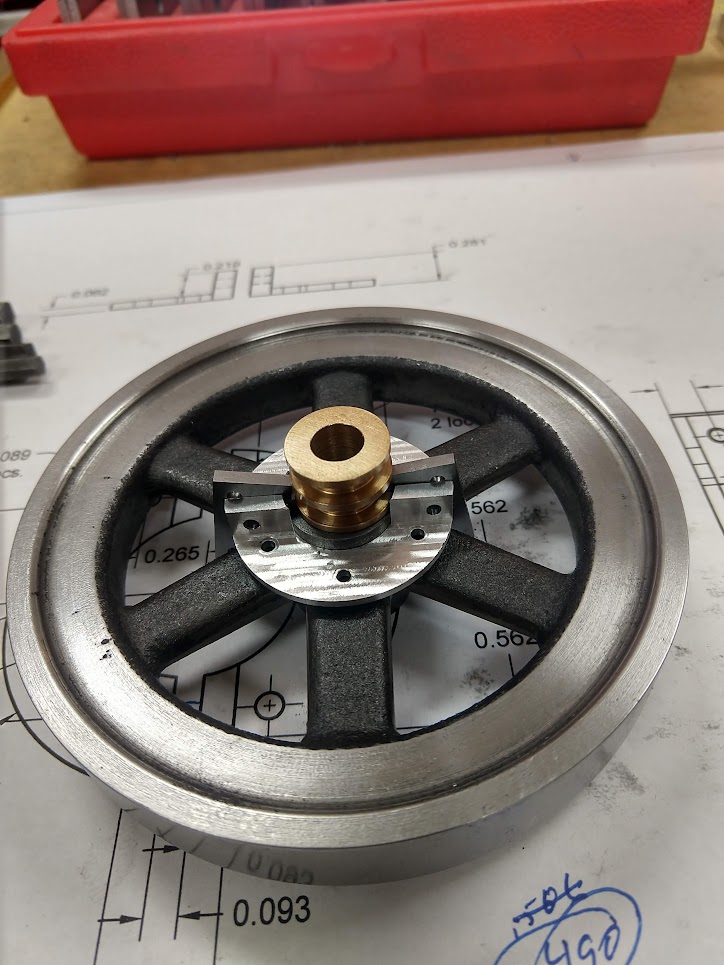
And here's how it will fit on the flywheel.  This is just showing the general arrangement.  I knew that I needed to trim down the hub of the flywheel and that became obvious when I started to fit it.


So it was back over to the lathe with the flywheel to reduce the height of the hub on the inner side of the flywheel.  I used a boring bar to do so as it could easily reach into the area and it cuts well.  I also machined the spoke area completely flat so that the carrier would fit securely on the flywheel.  I didn't want to mark up the OD of the flywheel but yet I wanted to not have a bunch of runout on the flywheel as I was machining the hub.  What I ended up using was as single layer of aluminum foil tape which is most commonly used for duct sealing.  This stuff is very sticky and is completely uniform in thickness at right at .004".  And it worked!  No marks on the flywheel OD after machining.  It's a good product and I'll certainly use it in the future. 


Then back over to the mill to drill and tap 6 locations 2-56 to hold the carrier.  I just centered the flywheel under the spindle and used xy coordinates to locate the holes.  Note that I continued to use the foil tape to protect the OD.  It continued to work!


Here's a mod to the flywheel that I had to do after I started trying to fit the hnm mechanism.  Since I used a cast flywheel, the hub and distance at the spoke hub webs was larger than Upshur's design.  So where the hnm arms are located I used a 3/16" end mill to remove the material at the 2 locations so that the hnm arms would close properly.


Here's part of the fitting process.  Everything mounted but the shoulder screws that I wanted to use were interfering just a bit on their heads.  Plus you'll note that they prevent the 2-56 mounting screws from being installed at 2 locations.


And here are some fitting mods to the hnm arms.  I rounded the ends and kept trying them until the fit the spool properly.  I also shorted the other short arms so that they'd allow movement toward the hub.  I had to do this since my hub OD was a bit larger than Upshur's original design. Rounding was done on a belt sander after bluing and marking with a radius gage. 


To cure the interference issue on the 2-56 screws, I made a couple of .093" pins out of drill rod and made grooves on each end of them to accept a 3/32" e-clip.  I didn't use anything fancy for grooving.  All I did was to grind down a bit of HSS to .020".  The grooving actually went very well as the tool was sharp and I didn't have to go very deep.  In case anyone hasn't used these very small e-clips before, my advise is to buy some extra ones as they are extremely likely to launch themselves into another dimension, never to be seen again, if you slip at all during installation or removal.  The best tool I found to use was a pair of the locking type of hemostats. 


Next was lots of assembly, trying, dis-assembly, fiddling around and repeating the cycle ad nauseum.  I'll show only a few pix of some of the more interesting tweaks that I ended up doing.

The first tweak that I did was to shim up the hnm lever in the camshaft slot.  For whatever reason it was fairly sloppy and my thinking was that was perhaps not moving freely as the end of it engaged at different places in the spool.  So I made a thin brass shim just by drilling and parting off a piece of .25" brass.  I was shooting for .012" and I managed to get pretty close.  Even the Queen nodded her approval. 


Here's the shim in relation to the hnm lever.


The next significan tweak was that I built in the end of the hnm lever with silver solder.  I got overzealous when I was shaping it and got it way too sloppy where it fit in the spool.  I just cleaned it with acetone, fluxed it and applied the silver solder to the end and then reshaped it.  Here's the lever after building it up.


Now that I managed to get everything moving freely and pretty well as it should be moving, I moved the hnm mechanism by hand first to its 'hit' position, that is low rpm and made sure that the lever did NOT engage with the stop.  That can be seen in this pix.


Then I moved the mechanism by hand to the 'miss' or 'ball-out' position and as you can see the lever clearly engages the stop which in turn locks the exhaust valve open.


And here's a view of the hnm mechanism fully installed showing the weights and springs in their 'hit' position. So far so good.


So, I was feeling good at this point and decided to run the mechanism with my drill motor as I could easily control the speed and could hopefully observe the hnm mechanism in action without the concern of actually trying to run the engine.  Well, let me tell you what NOT to do.  I had the ignition system all wired up but NOT secured in any way and had NOT paid attention as to where everything was laying.  So after some time, running the engine with the drill motor, the ignition wiring decided to leap into the hnm mechanism and you can see the result.


That's a destroyed plug wire, ground wire, and the worst thing was that the ground wire was ripped out by the roots from the S/S CDI module and there's no obvious way to solder it back as it's all heavily potted inside. 

So, what's next for our now incredibly stupid feeling small engine builder???

Stay tuned for the next post to find out the answer!

Mike
MIke
Wichita, KS, USA

Online Kim

  • Global Moderator
  • Full Member
  • *****
  • Posts: 7929
  • Portland, Oregon, USA
Re: Upshur Horizontal Farm Engine - Mike's Version
« Reply #65 on: November 15, 2021, 12:03:57 AM »
Aw man!  Sorry to read about your ignition wire catastropy!  That's no fun at all.  I'm sure you'll get it sorted and looking forward to see how you work it out.

Very nice work on the hit-and-miss mechanism, Mike!

Kim

Offline Don1966

  • Full Member
  • *****
  • Posts: 6818
  • Columbia, MS
Re: Upshur Horizontal Farm Engine - Mike's Version
« Reply #66 on: November 15, 2021, 12:27:45 AM »
Bummer about the ignition Mike, but if you have a solder iron use the point of it to dig into the potting of the ignition module you may be able to save it. At this point there is nothing to lose trying. Very nice work by the way.


Regards Don

Offline 90LX_Notch

  • Full Member
  • ****
  • Posts: 1614
  • North Eastern Pennsylvania USA
    • YouTube Channel
Re: Upshur Horizontal Farm Engine - Mike's Version
« Reply #67 on: November 15, 2021, 10:25:31 AM »
Sorry about the ignition mishap Mike.  Other than that, everything is looking great.

-Bob
Proud Member of MEM

My Engine Videos on YouTube-
http://www.youtube.com/user/Notch90usa/videos

Offline Admiral_dk

  • Full Member
  • *****
  • Posts: 3777
  • Søften - Denmark
Re: Upshur Horizontal Farm Engine - Mike's Version
« Reply #68 on: November 15, 2021, 09:48:06 PM »
Nice parts  :ThumbsUp:

And what a bummer with the Ignition  :hammerbash:  - haven't done that particular error, but my own list is long enough  :facepalm:

I can only agree with Don - many different kinds of potting epoxy formulas can be 'destroyed' with heat ....
So if your soldering Iron is temperature controlled - try around 150C first and increase if it doesn't touch it ....

Best wishes

Per

Offline propforward

  • Full Member
  • ****
  • Posts: 1656
  • MN, USA
Re: Upshur Horizontal Farm Engine - Mike's Version
« Reply #69 on: November 15, 2021, 09:51:12 PM »
Ooof! Sorry to see and hear about the ignition Mike. Alas - I do that kind of thing too often. I know you'll get that all fixed up, but vexing for sure.
Stuart

Forging ahead regardless.

Offline mikehinz

  • Full Member
  • ****
  • Posts: 355
Re: Upshur Horizontal Farm Engine - Mike's Version
« Reply #70 on: November 17, 2021, 10:57:04 PM »
All, thanks for the sympathy! 

After I managed to tear up my ignition wiring and pull the ground wire out of the CDI module by the roots, I started working on recovery from the mess. 

First I had to rewind the hnm springs as they were both destroyed.  This was actually fairly easy as I have the winding mandrel made and have a fairly decent winding guide for my lathe and I had plenty of .014" music wire left.  So I got the springs made and reinstalled on the engine.

Next I email Roy Scholl, the builder of the ignition system.  I sent him a few pix of the module and explained what happened.  Within a half a day, he emailed me back and suggested that I solder a new ground wire to the negative side of the LED.  That side of the LED is tied directly to the ground plane of the circuit board and is fairly easily accessible.  So that's what I did.  My backup plan was to dig out a bit of the potting material around the ground wire location using the tip of a hot soldering iron. 

Luckily Roy's advise was spot on!  So after rigging everything back up on the bench and testing with the spark plug removed from the engine but clipped in with a clip lead, I was extremely happy to see that I still had a good CDI module that still produced an excellent spark!  So I was now back to square one in terms of trying to get the engine working in hit-n-miss mode. 

I didn't take any pix of the process of working on the mechanism, but I did play around with spring tension quite a lot, all the way from changing to a much higher spring rate springs to going down to only one light spring.  What I found, like many others, is that heavy springs increase the engine RPM and lights spring lower it.  I also installed the small leaf spring as per Upshur's original plans.  That helped a bit, I think mostly because that spring makes the lever follow the spool's motion a bit better.  But I think it would be better to have an adjustable  spring in place of the leaf spring, as that would allow a bit of counter-action to the governors springs which would provide an easy way to adjust speed and to probably optimize the hnm mechanism and action. 

So, without further ado, here's what happened:

Here's the first run of the engine look at the hnm side so you can see the weights and springs in action:

<a href="https://www.youtube.com/watch?v=XUwN_to9GkM" target="_blank">http://www.youtube.com/watch?v=XUwN_to9GkM</a>

And here's a view of the engine from the other side with the hnm mechanism engaged and working:

<a href="https://www.youtube.com/watch?v=0J0nUNpUci0" target="_blank">http://www.youtube.com/watch?v=0J0nUNpUci0</a>

And lastly, here's a final video after I got the hnm mechanism working about as well as I could.  I'm sure it could be a bit better, but I think I'd have to redo the hnm lever to add and adjustable spring to it.

<a href="https://www.youtube.com/watch?v=z15DHkBOmu4" target="_blank">http://www.youtube.com/watch?v=z15DHkBOmu4</a>

So that it!  I'm declaring an end to this build!  I will install this engine on a nice wooden base and install a brass name plate on the base and I'll get that done in the next few days.  When that's finished I'll post the finished engine in the showcase portion of the forum.

Enjoy!

MIke
MIke
Wichita, KS, USA

Online crueby

  • Full Member
  • *****
  • Posts: 18687
  • Rochester NY
Re: Upshur Horizontal Farm Engine - Mike's Version
« Reply #71 on: November 17, 2021, 11:03:12 PM »
Wow - nice recovery!!  Love the sound of it, very well done!    :ThumbsUp: :ThumbsUp:

Offline Brian Rupnow

  • Full Member
  • *****
  • Posts: 7610
  • Barrie, Ontario Canada
Re: Upshur Horizontal Farm Engine - Mike's Version
« Reply #72 on: November 17, 2021, 11:09:45 PM »
Nice job Mike. Reminds me a lot of what I went thru when I built the Kerzel hit and miss engine. I have three or four different hit and miss engines, but they are all running viton rings. I think the Viton ring cause considerably more drag than cast iron rings, so my miss cycles were never as long as I wanted them to be.----Brian

Offline RReid

  • Full Member
  • ****
  • Posts: 1699
  • Northern California
Re: Upshur Horizontal Farm Engine - Mike's Version
« Reply #73 on: November 17, 2021, 11:31:18 PM »
Congratulations Mike, job well done! :ThumbsUp: :cheers:
Regards,
Ron

Online Kim

  • Global Moderator
  • Full Member
  • *****
  • Posts: 7929
  • Portland, Oregon, USA
Re: Upshur Horizontal Farm Engine - Mike's Version
« Reply #74 on: November 18, 2021, 12:12:10 AM »
Congratulations, Mike!  Your engine runs great!
Love the sound of that hit-n-miss.

Glad you found a good solution to your quandary.

Kim


SimplePortal 2.3.5 © 2008-2012, SimplePortal