Thanks for stopping by and thanks for your comments.
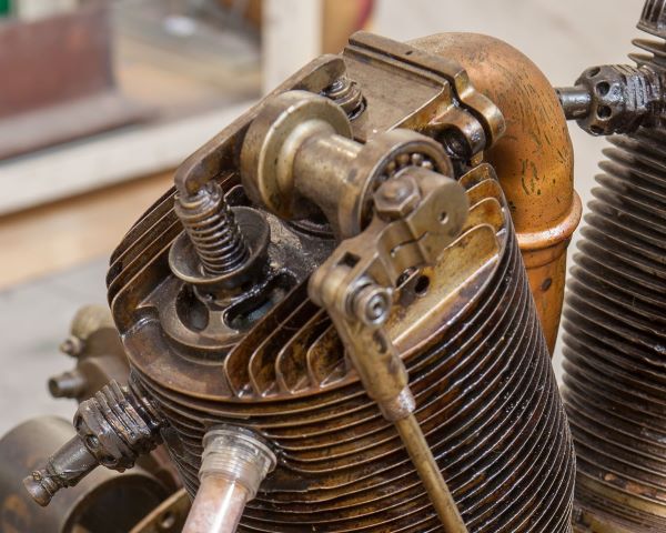
I made a few more of the cylinder head bases today. It occurred to me that some of you might be having problems trying to visualize exactly what Im trying to accomplish. To help you out I thought Id supply a bit of background. Firstly, below is a photo of a cylinder head on a full size Le Rhône. This is for a Le Rhône 9J (not 9C) so a few things are backward since the placement of the pushrods are at the rear of the engine case (as opposed to the front with the 9C).
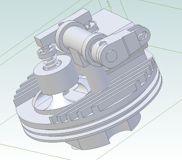
Below is a rendering of the head Im building as rendered by my CAD system.
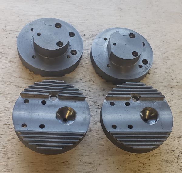
To fill out the background; below is a photo of the exploded parts that will go together to make my cylinder head. Obviously, Im currently working on the base part. On the full size, the intake and exhaust parts are integrated as part of the cylinder casting.

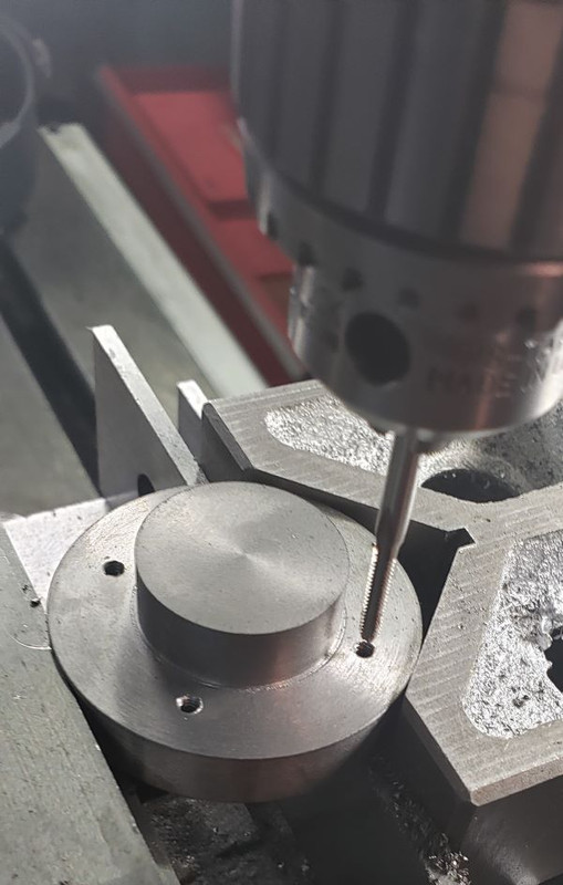
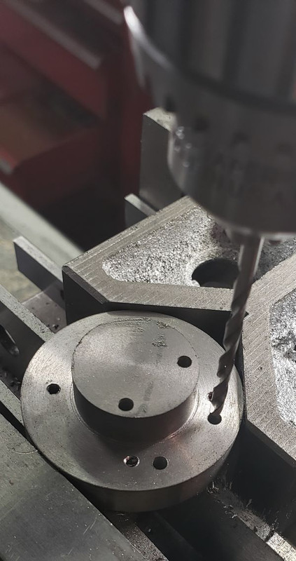
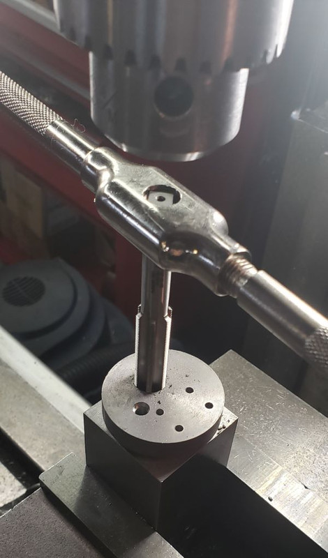
The first step in fabrication of the head base is to drill and tap the holes that will be used to attach this cylinder head to the cylinder. On the full size, the cylinder head and cylinder are integral but Im making them separate in order to simplify the construction of the engine.
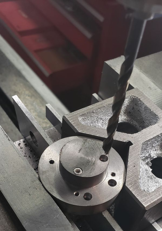
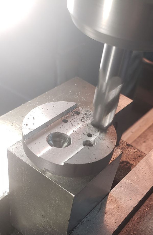
Next, Im drilling the holes that will allow thru bolts to attach the intake part of the cylinder head to this cylinder head base. On the full size, this is integral to the cylinder casting.
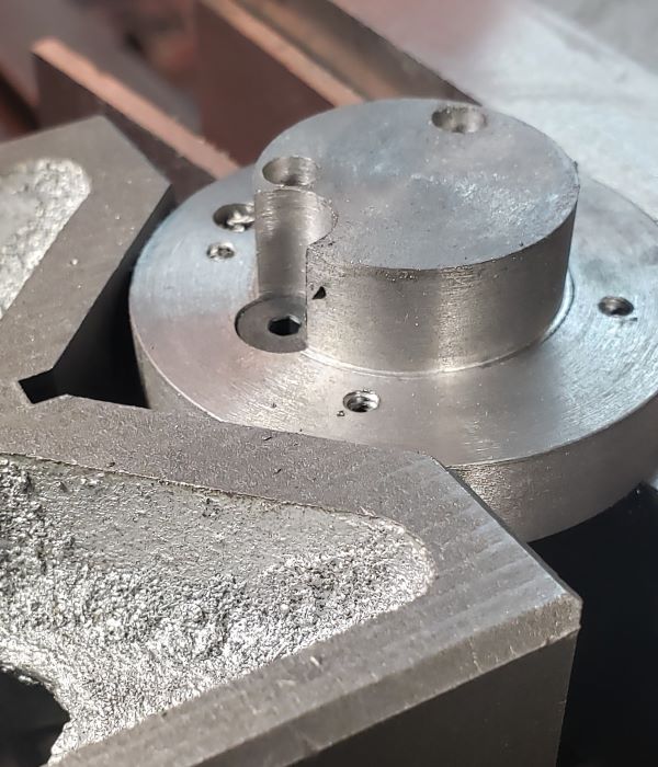
I need these thru bolts to be flush to the bottom of the head so that the cylinder dead will seal when attached to the cylinder, so Im cutting a recess so a cap screw will fit flush to the bottom of the head (where it attaches to the cylinder). I've placed a cap screw into one of these holes to help you understand what I'm trying to accomplish.
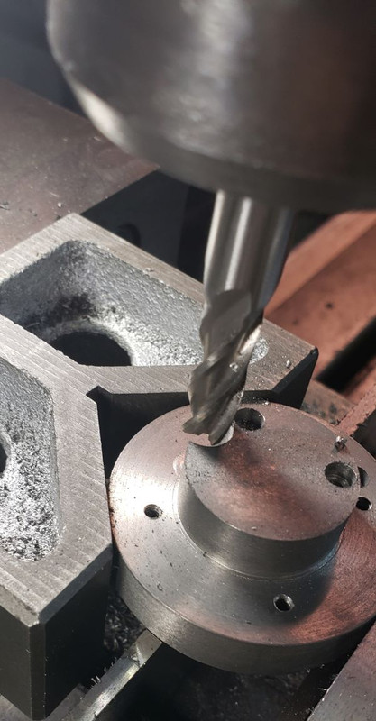
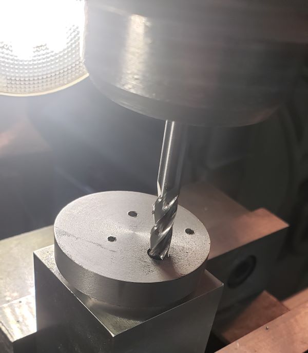
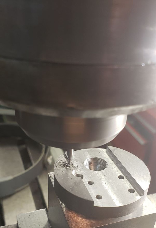
Another thru bolt attaches the part that holds the rocker arm to the top if the cylinder head. I cant use a drill to cut away this material, so Im using an end mill.
Once again, I need to recess the head of the bolt, so Im cutting a recess.
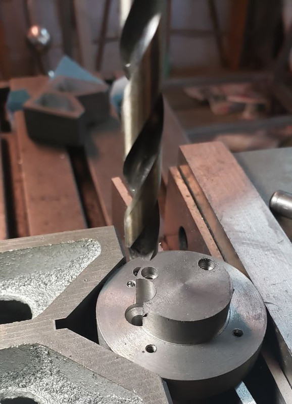
A view of the fit of the recessed bolt.
Now Ive turned the head base over and am holding it in a 5C collet so I can machine the top of the part.
The rocker shaft support attaches to the head using a bolt threaded through the hole formed as shown in the previous photo. On this top side, I need to cut away the material so the rocker shaft support will fit up against the top of the cylinder head. I need to cut away the material that occupies the area that will be part of the cylinder head fins.
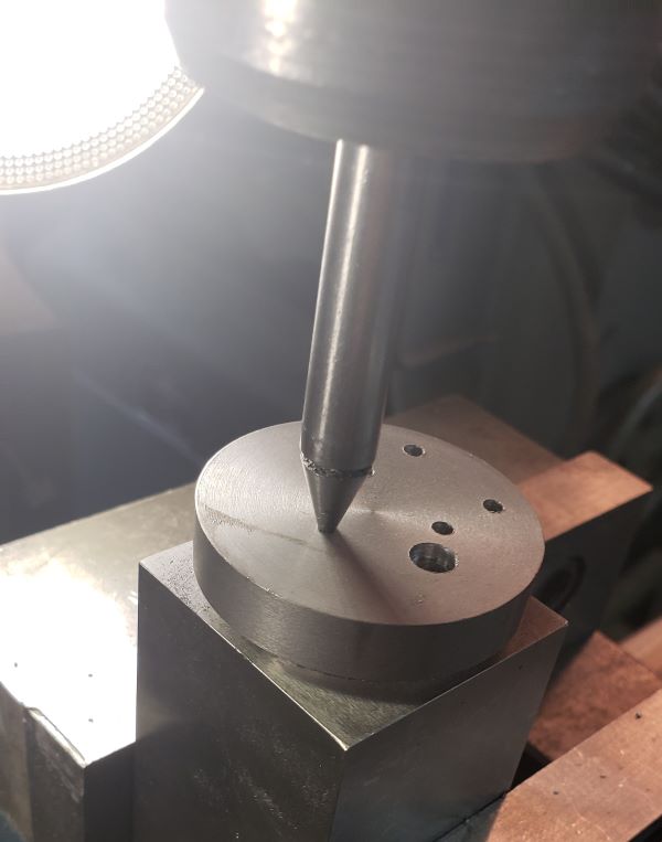
Here Im locating the center of the orifice that will be used to attach the exhaust part. That part will attach to the top of the cylinder head. Im not cutting the valve guides or valve seats until I assemble the exhaust and intake parts of the cylinder head so I can be assured that everything will be in alignment.
The exhaust part of the head screws into the head base part. Here Im cutting the threads that will be used for that attachment.
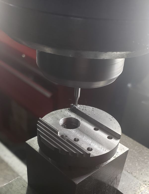
Time to cut in the fins on the top of the cylinder head. Here Im cutting in the center relief.
Starting on the first fin. Im cutting these with a 1/16th inch diameter end mill to a depth of 3/32 inch. Im using three passes, cutting a depth of roughly .030 inches per pass, which is around half the diameter of the end mill. Probably cant push the end mill harder than that.
One side of the head fins complete, starting of the other side
Just completing this head base.

Four cylinder head bases complete, well almost. Once I get the intake and exhaust parts of the head fabricated and attached to these bases I can machine the valve guides and valve seats. Once that is complete Ill need to cut the two fins on the cylinder head base diameter. Were I to cut these fins now, the head would be too fragile to hold to complete the machining.