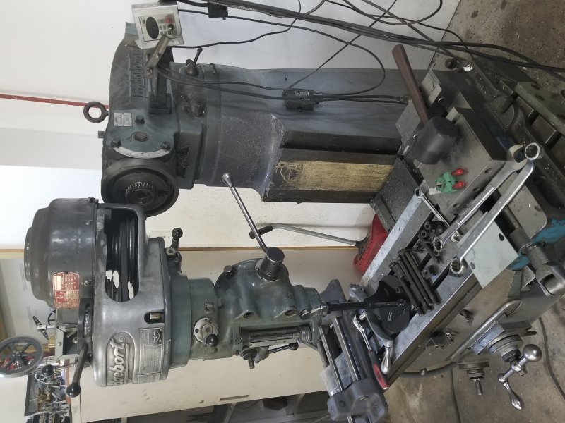
I have been living with not having back gear for a number of years, and then when I tilted the head to try to drill at an angle the spindle wouldn't turn. After watching several YouTube videos from H&K on teardown/rebuild/and reassembly of the upper section, I decided to send the entire head to H&K for a rebuild of the top and inspection of the lower spindle section. Rather than struggle with the entire 200 lbs of head, I planned to disassemble the upper half following the videos, and deliver the parts myself (one day drive from home).
The first issue was removing the head from the ram. To do this, I ordered their ram removal tool from H&K. It's basically a fixture that bolts the table using t-nuts, and has a vertical 7/8" diameter vertical rod at the top. A 7/8" collet is inserted into the spindle and locked to the fixture prior to bolting to the table. With everything tightened up, the 4 nuts that secure the ram bolts are removed, and then the table is retracted. The bolts are quite long, so I also had to retract the ram to clear them from the head.
Now I could lower the knee to the bottom and start the disassembly with the head still clamped to the table. The removed sections are the motor and 1 set of pulleys, the pulley enclosure, the front pulley assembly, and the bull gear section. I'll leave the spindle section on the fixture until time to load the car.
One thing I noticed through experiment is that it could be difficult to reattach the head to the ram even with the tool. That's because the 4 t-bolts that need to line up are free to rotate and wiggle, and unless lined up perfectly with their holes will jam solid. Not having Chris' elves to station one per bolt, I decided to make an alignment fixture to hold all 4 simultaneously in position. This fixture is a piece of cardboard with 5 holes, and is show in position with the bolts about halfway into the head.
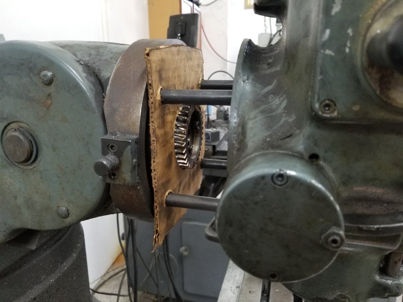
To prepare to use it, the head is positioned on the table and moved into the ram so that the ram's helical gear enters the matching cavity on the head. The the t-bolts are inserted and moved so that the cardboard can be inserted over them. With the cardboard's hole over the ram's gear, it was fairly simple to guide the bolts into the head. Once the bolts are well in, I'll cut away the cardboard.
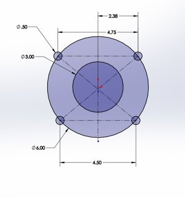
To make the fixture, I measured the head and produced this drawing in Solidworks.
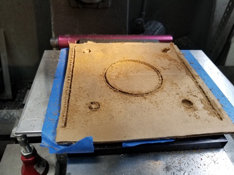
I cut the holes into a 7" square piece of 1/8" thick cardstock on my CNC mill as follows.
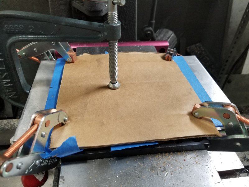
With a 6" wide piece of aluminum in the vise, I put three strips of 3M painters tape on top. These were burnished to remove any bubbles/wrinkles.
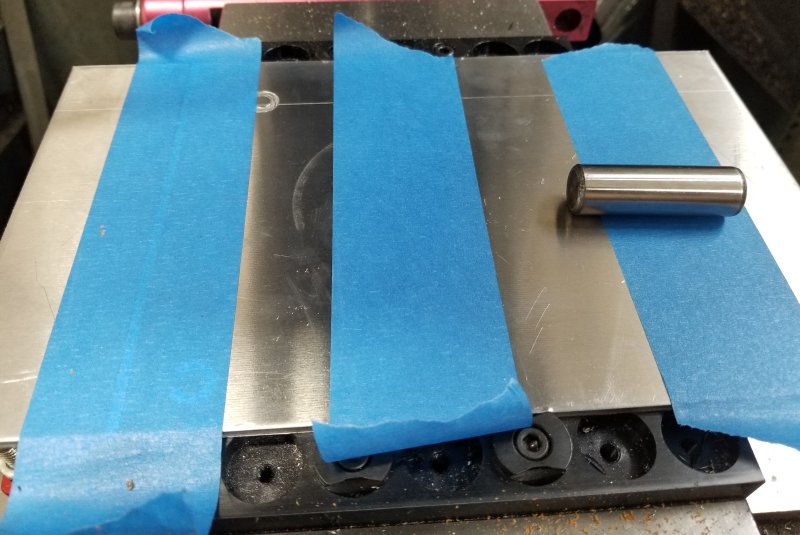
I spread some Loctite glue along both sides and a small amount in the center, then centered the cardboard and clamped. I waited 30+ minutes for the glue to set.
Not too difficult to remove the tape from the aluminum freeing the fixture. Nothing too pricise here other than the holes.


