Author Topic: Chris's Holly Pumping Engine Build  (Read 155373 times)

Offline crueby

  • Full Member
  • *****
  • Posts: 18666
  • Rochester NY
Re: Chris's Holly Pumping Engine Build
« Reply #1455 on: October 19, 2021, 06:20:08 PM »
Okay, as promised, here is the start of the globe valve. It is not that different from ones posted by others on the forum in the past, with the main difference being that it has a bottom cover plate that lets the valve stem come in from that side. The reason I am doing this is that it matches the one on the original Holly engine more closely. Also, the way things worked out, it requires no silver soldering, the pieces just screw together, so its a bit simpler to make.


I need one of these for this engine, but know that I'll need more for the next engines in the pipeline (valve, pipeline, ....  :Lol: ) so I am making up a set of four while I am at it - once a setup is made and cut depths/diameters are dialed in, it does not take much longer to make a set than one.

The plans in PDF form are attached to this post - if it turns out that there are changes later on I'll repost the plans.

I'll go through the process step by step for those that want to make this valve. So far I have the main body just about done, the rest of the parts should be ready later today or tomorrow.

To start, I turned some brass bar to 5/8" diameter (did not have that size, so turned down some 3/4" bar) and trimmed all of them to the same length. Having them the same length let me calculate the distances in from the end of the bar once, and could use the same setup as long as each bar was positioned the same on the vise or in the chuck. Then drilled a starter hole in each end, with the tip of the drill going the desired depth of the hole. The bars were made long enough to grip in the chuck from either end. This comes in really handy later when the center is turned to the globe shape.


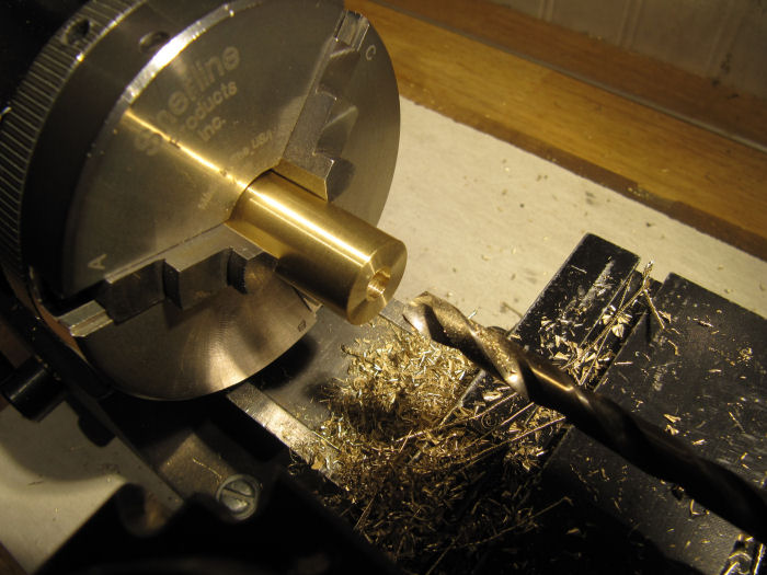
Then used a small boring bit to take the holes out to 0.300" diameter the depth of the hole.

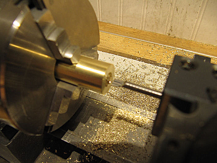
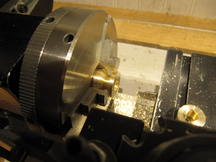
With the bars all the way into the chuck, I offset from the end with the parting tool and cut the straight section between the globe and the flange. If you have a larger chuck, you could put in a chuck spider to position each the same. With them all at the same position, the same long-axis position for the lathe table hit the same spot on the part, making it quick to cut all the straight sections the same.

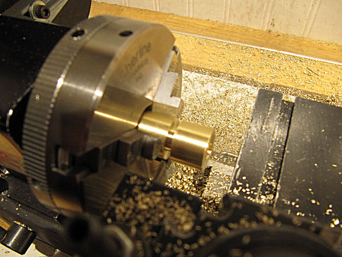
Then went around the parts again to make a shallow cut for where the outside of the flange will be. This is where the bars will be parted off later.

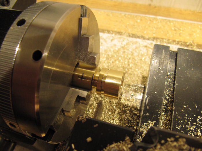
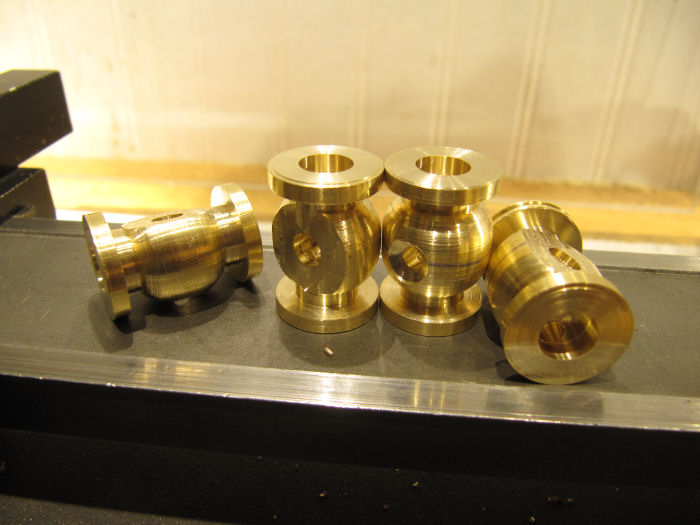
The parts so far. If you look close you can see a boo-boo on the lower one, I goofed on the first cut on the first bar. That one will have its flange turned a little smaller and have a smaller hole pattern later on, which saves the part. I used that bar for the first cut on the rest of the steps just in case of another goof.

Switched to a pointy lathe tool, and turned in the ends of the globe sections. Done by hand, etch-a-sketch style. The globe shape is not critical. A short flat was left in the center to aid in holding in the chuck later.

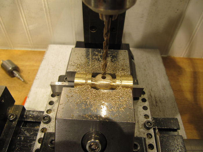
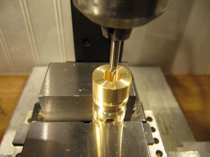
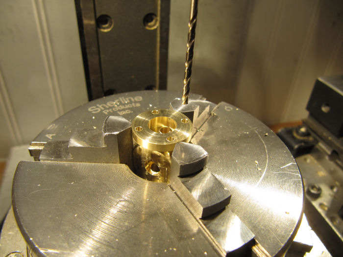
Now over to the mill. Centered the part under the mill head, and drilled each with a #30 drill (.128") all the way through. This will be tapped on one side later to an M4 thread to hold the stem post.

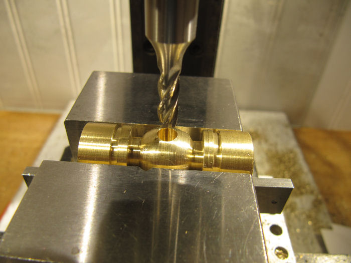
With the part still in the vise, then used a 3/16" end mill to plunge cut .550" deep to form the valve seat.

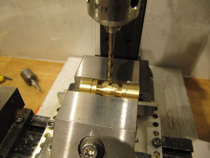
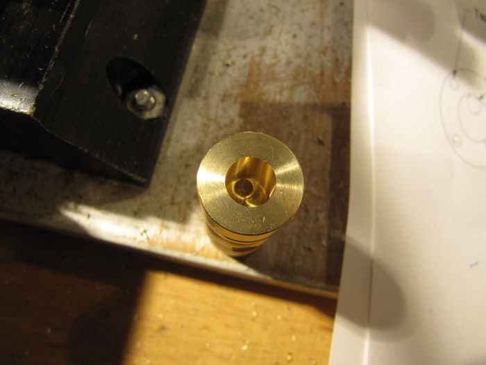
Now the parts were turned over, and the same #30 drill bit was used to get them aligned with the hole vertically again. The 3/16" diameter hole is now on the bottom.


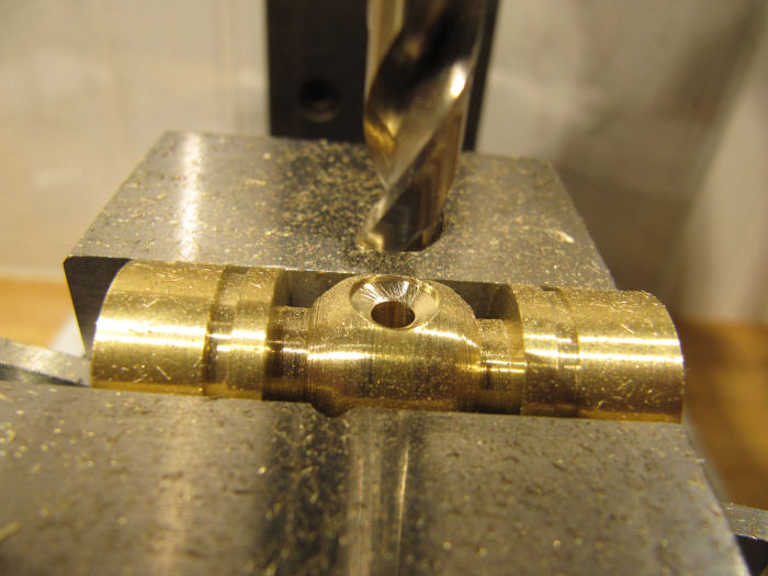
Then used a letter F drill, 0.257", to drill a shallow shoulder into the top of the part. This will let the stem post sit down flush with the top curve. This hole was drilled just deep enough to meet the curve of the part. Could have set up on the lathe and used the boring bar to get a flat there, but this was quicker.

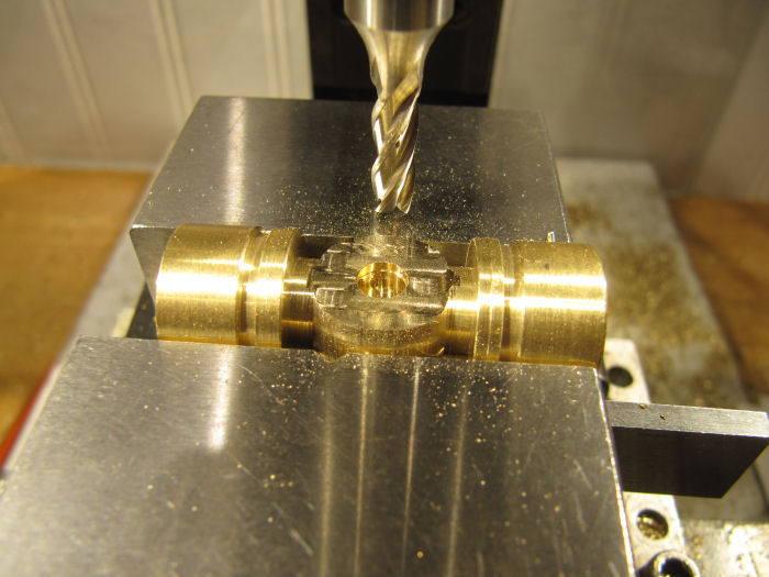
Now turned the part on end, and drilled a hole along one edge of the bore into the center hole. There is one hole on either end, one at the top of the bore, one at the bottom of the bore, this forms the passages for the steam/air.

Ah - realized I forgot to include the cutaway view, this will make what I am doing clearer:


Here is a view in from one end to show the hole:

Next the parts were put in the vise horizontal again, with the bottom side facing up. The bottom was milled off to form the seat for the bottom cover pieces. This cut was taken down to just above the diameter of the straight ends by the flanges.

The parts so far:

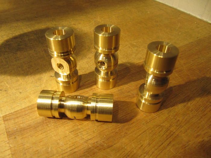
Good time to part off the excess bar on the ends:

Leaving the parts looking like this:

Right now I am in the middle of drilling/tapping the 1-72 holes in the flanges. Another set of holes will be drilling into the flats on the bottom, to match the bottom covers to be made later.

More to come...

EDIT - updated plans, there was one missing dimension on the last page
« Last Edit: October 20, 2021, 07:32:55 PM by crueby »

Online cnr6400

  • Full Member
  • *****
  • Posts: 2777
Re: Chris's Holly Pumping Engine Build
« Reply #1456 on: October 19, 2021, 08:32:34 PM »
 :ThumbsUp: :ThumbsUp: :ThumbsUp: :popcorn: :popcorn: :popcorn:
"I've cut that stock three times, and it's still too short!"

Offline steam guy willy

  • Full Member
  • *****
  • Posts: 3245
Re: Chris's Holly Pumping Engine Build
« Reply #1457 on: October 19, 2021, 08:57:30 PM »
Hi Chris, thanks for the diagram etc looks like lots of use available to take up for wear ??  cool

Willy

Offline crueby

  • Full Member
  • *****
  • Posts: 18666
  • Rochester NY
Re: Chris's Holly Pumping Engine Build
« Reply #1458 on: October 19, 2021, 09:07:06 PM »
Some more done on the globe valves, the bottom caps and bases turned on the lathe and clearance drilled for 1-72 screws.

Rather than spend a bunch of time centering up the valve bodies in the 4-jaw to locate the base cap screw holes, I just ran in a 5-40 screw with nuts either side to hold the base piece to the body, then used that as a drill guide. Went around once with the clearance drill to spot the locations into the base, then again with the 1-72 tap drill and went in .400" on each.

Tapped each hole in the base and the flanges, here is valve number 1 so far.

Good place to break for the day. Tomorrow should be able to knock out the valve stems and the stem posts, then be able to give them a test. Pretty straightforward so far, hope they work!   ::)

Offline ddmckee54

  • Full Member
  • ****
  • Posts: 642
  • We're having fun now --- or so I've been told.
Re: Chris's Holly Pumping Engine Build
« Reply #1459 on: October 19, 2021, 09:20:32 PM »
and they drilled the back wall of the safe....   :facepalm:

There's no doubt about it Chris, you need to get a better safe.  And keep all the carbide drills locked in the new safe, along with your credit card.
Don

Offline ozzie46

  • Full Member
  • ****
  • Posts: 343
Re: Chris's Holly Pumping Engine Build
« Reply #1460 on: October 19, 2021, 11:34:12 PM »
Everything is magnificent. I don't say much cause my drooling woukd short circuit my keyboard.  :pinkelephant: :pinkelephant: :pinkelephant:

Thanks for the globe valve drawings

Ron

Offline crueby

  • Full Member
  • *****
  • Posts: 18666
  • Rochester NY
Re: Chris's Holly Pumping Engine Build
« Reply #1461 on: October 19, 2021, 11:40:22 PM »
Everything is magnificent. I don't say much cause my drooling woukd short circuit my keyboard.  :pinkelephant: :pinkelephant: :pinkelephant:

Thanks for the globe valve drawings

Ron
Thanks Ron!  Do what I do when reading threads like the Le Rhone engine, put a towel around your neck to catch the drool!   :lolb:

Online Kim

  • Global Moderator
  • Full Member
  • *****
  • Posts: 7916
  • Portland, Oregon, USA
Re: Chris's Holly Pumping Engine Build
« Reply #1462 on: October 20, 2021, 12:30:22 AM »
Very interesting step-by-step on the ball valves Chris! Can't wait to catch the next episode :)

Kim

Offline Don1966

  • Full Member
  • *****
  • Posts: 6817
  • Columbia, MS
Re: Chris's Holly Pumping Engine Build
« Reply #1463 on: October 20, 2021, 01:27:00 AM »
Do they call you  Rocket man? Your life a rocket none stop and totally engaged…….amazing progress Dog……. :Love:


 :drinking-41:
Don

Offline crueby

  • Full Member
  • *****
  • Posts: 18666
  • Rochester NY
Re: Chris's Holly Pumping Engine Build
« Reply #1464 on: October 20, 2021, 04:19:44 PM »
Thanks Don/Kim!

For todays episode, more on the globe valves. The bodies are all tapped, including M4 for the top stem post. Turned a length of round bar to the .257" for the top flange, and threaded the end M4. The inside edge was shaped down at an angle and that end also turned to size for threading M4. The pieces were also drilled through with a #50 drill for the 2-56 valve stem thread.


Sorry for the blurry picture on that one!
Then each post was parted off. Once I had all four that I needed, the end of the round bar was drilled/tapped M4 so I could turn the posts around and thread the other end. The outer .1" was counterdrilled with a clearance drill for 2-56 to let the smooth part of the stem stick farther down in, so the packing on the packing nut would ride against a smooth surface.

Here is the first one test assembled on the valve.

still three more posts to thread the outer end on, then can start in on the packing nuts and the valve stems. First, off to lunch with some friends!
 :cheers:

Online Kim

  • Global Moderator
  • Full Member
  • *****
  • Posts: 7916
  • Portland, Oregon, USA
Re: Chris's Holly Pumping Engine Build
« Reply #1465 on: October 20, 2021, 05:28:45 PM »
Looking great, Chris!   :popcorn:

So, just to be clear, you WON'T be silver soldering that ring to the body of the valve?  (Since you said no soldering?) Will there just be a gasket between the body and that ring?  And between the ring and the cap?

Kim

PS Sorry the writing looks like I wrote it with a potato... I actually used my mouse, I'm just not good at mouse writing apparently :)

Offline crueby

  • Full Member
  • *****
  • Posts: 18666
  • Rochester NY
Re: Chris's Holly Pumping Engine Build
« Reply #1466 on: October 20, 2021, 06:20:28 PM »
Looking great, Chris!   :popcorn:

So, just to be clear, you WON'T be silver soldering that ring to the body of the valve?  (Since you said no soldering?) Will there just be a gasket between the body and that ring?  And between the ring and the cap?

Kim

PS Sorry the writing looks like I wrote it with a potato... I actually used my mouse, I'm just not good at mouse writing apparently :)
Yup - could be soldered, but I figured I'd just put some of the gasket-maker goop in there to seal it up. That base ring could have been made as part of the outer cap with a scribed line to mimic the cap joint, but it was quicker to keep it two pieces. A few more parts to make and I can find out how well they work - I want to use it to test out the cylinder valves too, so will make a short adapter pipe. The top/bottom inlet pipes on the cylinder are connected with external pipes, with curved elbows. I found a 1/4" copper elbow at the plumbing store that I will adapt to make the pipe elbow, will add flanges either end soldered on and trim the ends shorter.
A fun side project from the bigger model!

Offline crueby

  • Full Member
  • *****
  • Posts: 18666
  • Rochester NY
Re: Chris's Holly Pumping Engine Build
« Reply #1467 on: October 20, 2021, 07:35:00 PM »
Hi all,
For any who already download the plans pdf for the globe valve, I found one bad dimension on the last page, for the height of the valve stem end. Updated the original post with the corrected version (0.8) and also attaching to this post. So far everything else is okay, down to making the valve stems and the handwheels....
Chris

Offline Dan Rowe

  • Full Member
  • ****
  • Posts: 1170
  • Dripping Springs TX USA
Re: Chris's Holly Pumping Engine Build
« Reply #1468 on: October 20, 2021, 08:05:40 PM »
Hi Chris, am I missing something or did you use a left hand thread on the valve stem? It seems to me that clockwise rotation will open the bottom seat valve. This would make me crazy clockwise should close a valve and it is wired into my hand and brain so no matter how the valve is mounted I know how to open or close it.

Cheers Dan
ShaylocoDan

Offline crueby

  • Full Member
  • *****
  • Posts: 18666
  • Rochester NY
Re: Chris's Holly Pumping Engine Build
« Reply #1469 on: October 20, 2021, 08:22:03 PM »
Hi Chris, am I missing something or did you use a left hand thread on the valve stem? It seems to me that clockwise rotation will open the bottom seat valve. This would make me crazy clockwise should close a valve and it is wired into my hand and brain so no matter how the valve is mounted I know how to open or close it.

Cheers Dan
Nope - you are not missing something, and yes its a right hand thread on the valve stem, since I don't happen to have a left-hand 2-56 tap/die set in the box. On the blueprints for the full sized Holly valve, they show a right hand thread, 4-tpi square thread. So, I can claim accuracy to the original for that....  ::)   Thats my story and I'm sticking to it. Till I forget it anyway!   :Lol:

A good note for those that might make this valve for thier own use, if you have a left hand tap/die set for the stem, use it if you like!


I'm hoping it will keep the shop elves from using the engine too much if they can't figure out that the valve works opposite!  Ooops, just remembered, they read this forum....  :facepalm:


SimplePortal 2.3.5 © 2008-2012, SimplePortal