So, in thinking, plotting, planning, mind-changing, and all round procrastinating on the flywheels, I finally settled on how things would be done and how it would be held. Many ways to do it, this one seems to be working out so far. The desire was to use a taper lock for the hubs, but the hubs are fairly small diameter and there is not much width around them available, so it wound up being a slightly modified version of the usual lock design. Putting the taper into the hubs directly is not practical on my machines, since the lathe won't swing this large a piece (raw casting is 8" diameter, finished flywheel is 7.5" diameter) so that I can use the normal compound rest. What I wound up doing is not ideal, but works fine for a low-rpm engine like this one. I replaced the crankshaft on the lathe between centers and turned a shallow taper into the flywheel bosses, narrow end out to the outsides so the locks could be slipped on from the ends.
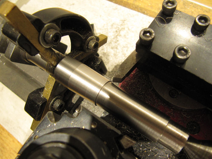
Then, with the compound rest still locked into its angle (3 degrees, any steeper and it would not take advantage of the full width) I also turned a mandrel that will stay locked into the four-jaw for the duration of these steps.
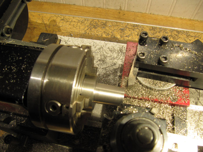
Both those operations were on the outside of the parts, the compound rest works with the cutter inverted and on the back of the cross slide. For the next steps, cutting the internal tapers on the locks, I switched to a boring tool held in a little adapter I made several years ago that holds the tool at the right hieght for cutting internally on the normal front side. The holes were first bored straight through to the size matching the small end of the taper. Then, cut on the taper angle to widen the outer end far enough to match the lengths of the tapers made on the crankshaft and the mandrel. The mandrel was used to check the size of the hole.
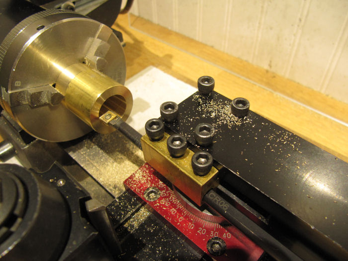
The turned the outside of the locks (making two of these, one for each flywheel) down to the size that I am going to bore in the flywheels. This is a straight parallel cut.
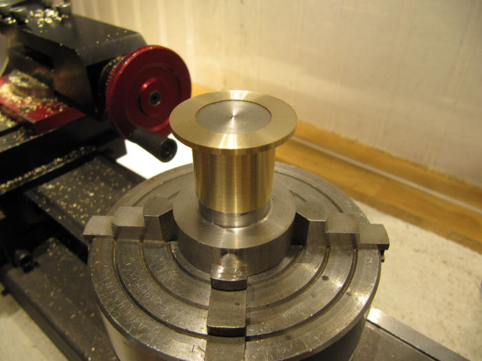
After parting off, here is the taper lock sitting on the mandrel - perfect fit, angles match.
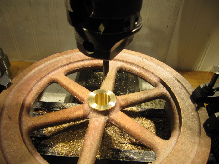
Now on to the first flywheel. The castings (from Martin Models) are bronze, and they are quite even, just a little of the usual offset between the sides, and the surfaces are pretty good for castings. I found a spot where it would sit level on the mill table, with blocks under each end to let me bore through without hitting the table. After clamping down with four step clamps, the end of the hub on that side was milled off flat - it had an '8' cast into it from the foundry.
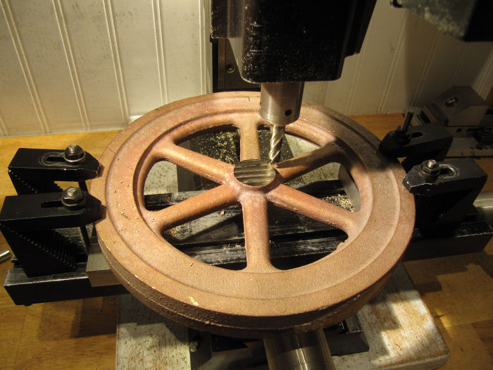
I used the co-ax indicator to center the hub under the mill head, and locked down the mill table.
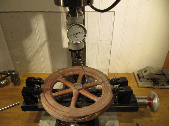
I checked both the edge of the hub and the edge of the rim, they matched within the size of the casting bumps. Next step was to drill a starter hole and begin boring out the center...
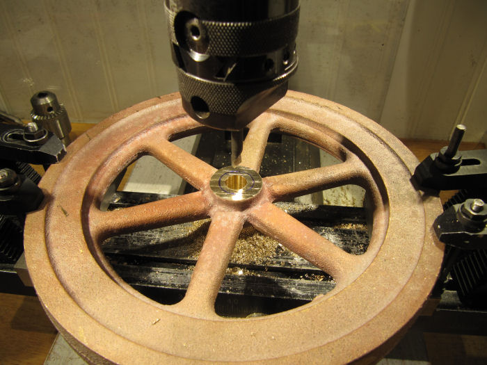
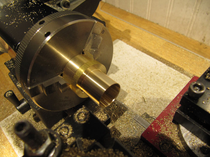
A 'boring' while later, the hole was sized to be a snug fit on the taper lock.
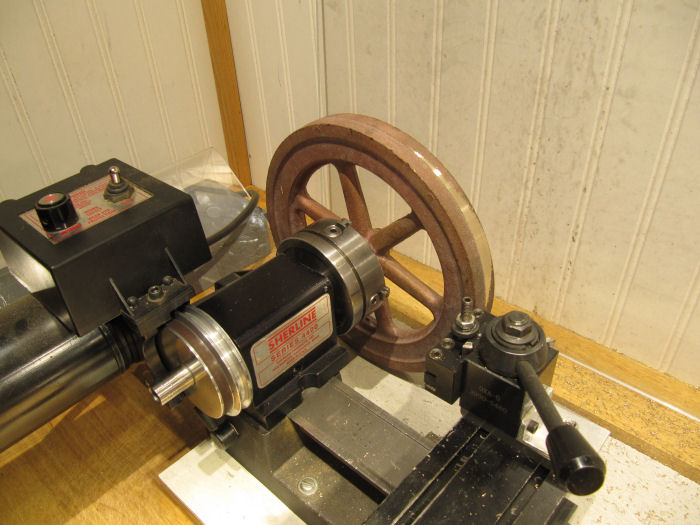
Then turned the headstock on the lathe 90 degrees and chucked up the flywheel - checked the tightness on the hub several times, and hand-spun the wheel to make sure it was all solid. All good, and running pretty true, so I started some light cuts to take off the uneven-ness.
Both sides and the hub look to be pretty close, so that is good. Really glad I went for the bronze casting - no hard spots on the surface to deal with and no black powder like with cast iron! The sprue location took a few extra passes.
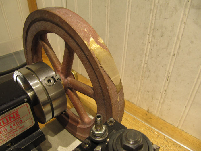
Once the high spots were off I could up the rpm a little more as it got into full cuts. Going to take a while to get it down to size - need to take the OD from 8" to 7.5", and the rim width from 7/8" down closer to 1/2". This casting was the closest I could find to the size needed for this engine.
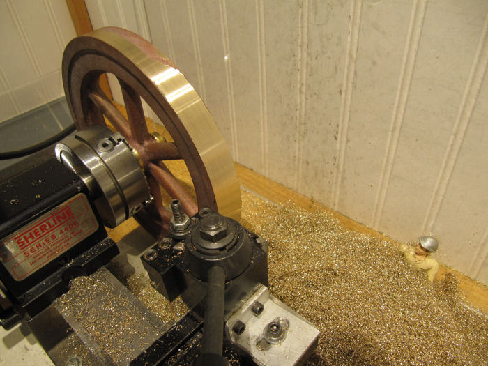
As you can see in that picture, the shop elves loved how soft the bronze wool coming off the cuts was, and decided to take a bath in it...
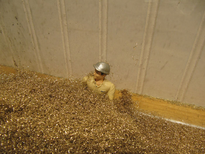
Cleanup will be easy, the shavings collect in a mat that can be picked up in one big carpet.


