Author Topic: Chris's Holly Pumping Engine Build  (Read 155366 times)

Online crueby

  • Full Member
  • *****
  • Posts: 18665
  • Rochester NY
Re: Chris's Holly Pumping Engine Build
« Reply #780 on: July 14, 2021, 09:39:33 PM »
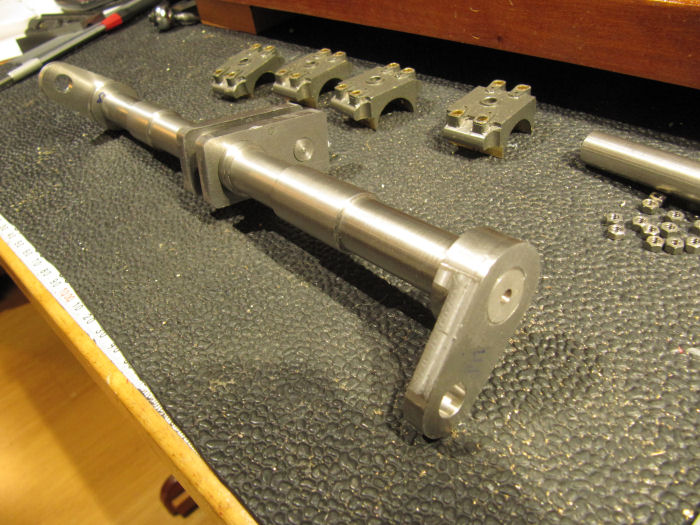
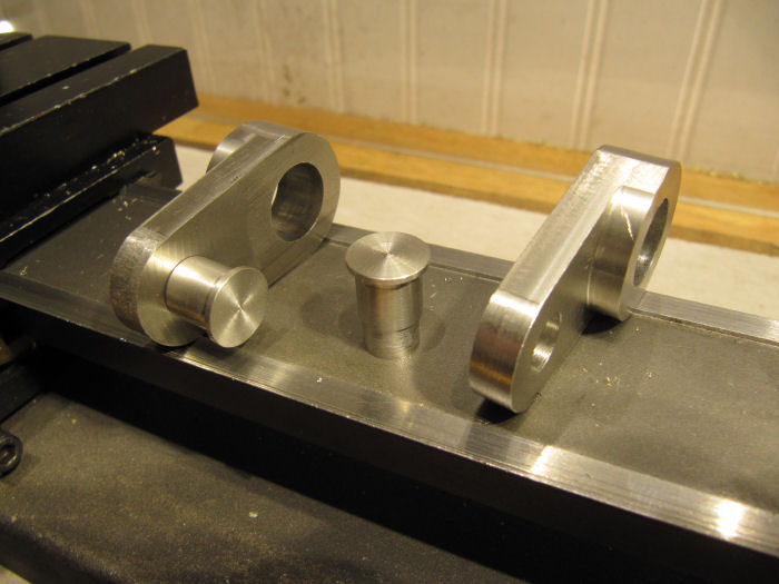
Last update yesterday I was working on the end crank webs. Since then finished up both of them, here they are set in place on the crankshaft (cant affix them yet, till flywheels and gear go on)


Then turned the crank pins - these were loctited into the ends of the webs, will be taper-pinned in place in a couple days.

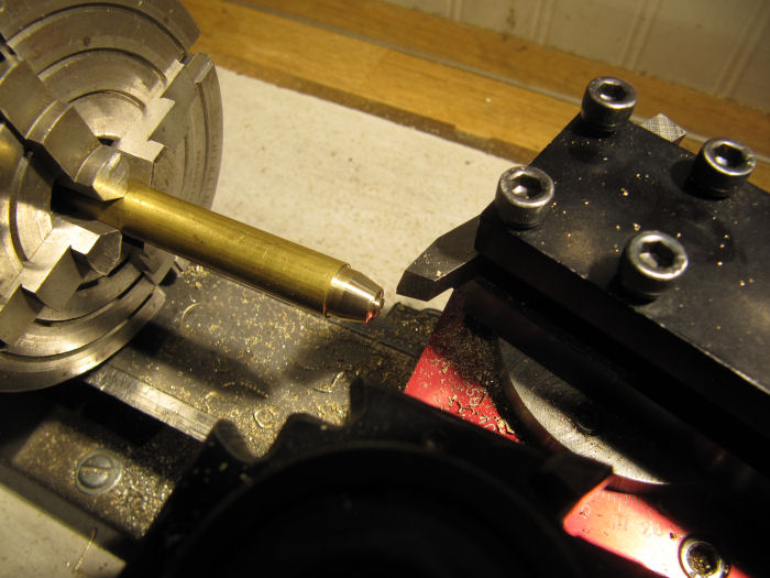
Then I decided to start on the bevel gears. Since the model needs two matched sets, one on the crankshaft and another at the lay shaft, both pairs will be made at once. They are 12 and 54 tooth bevel gears, with a 77.5 degree cone angle, cut with a Module 0.6 cutter set. After going through the spreadsheets created a couple years ago with help from several others on this forum to get the math done, I set up to cut the small pinion gears first - if anything went wrong, its not much work or material wasted! So, started with the compound rest on the lath to make the blank for the first one:

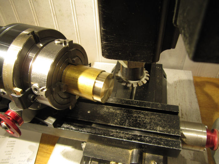
and set up the rotary table at the same angle on the mill to cut the teeth. I'll be using the parallel-depth process, which normally uses three passes to shape the teeth. Since these gears are such a small size I am skipping the initial pass and going straight to the second and third passes - with larger teeth the first pass takes out the bulk of the material and the other two shape in the teeth to final angles, but with such small teeth there is very little taken on the later passes that I can skip the first step - read about that in one of the books, and it worked.

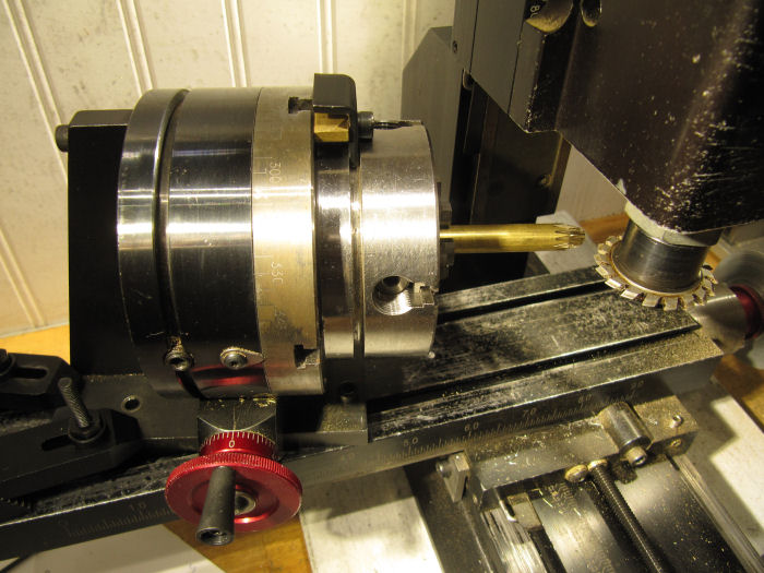
And went around the blank cutting the 12 teeth.

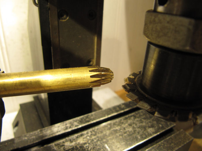
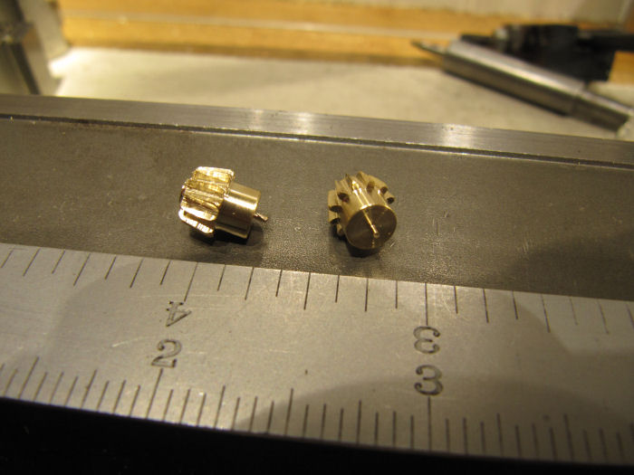
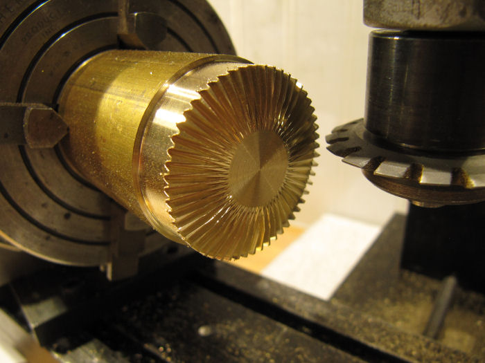
At this point I could tell something was very wrong - the tops of the teeth were little knives, very little width to them. Went back and checked the spreadsheet, checked the dimensions, depth of cut, all that. Several times. Then realized the problem - all the handwheels, including the rotary table, on the Sherline have 5 major ticks and 10 minor ticks per major one - I am very accustomed to that. BUT - the compound slide with its very small scale has 5 major ticks and just 5 minor ticks per major one. That means I wasn't at the 12.5 degree angle I wanted, but at 14.5 degrees instead.   :zap:   So, the taper was too steep, which meant when I set the depth of cut out near the tip, the cut was way too deep at the base.  As the Mythbusters would say - THERES your problem! 

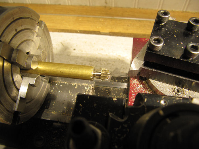
Fortunately it was not much lost, so I cut the end off the blank and tried again with the proper angle on the lathe (the angle on the mill was fine, that was set with a fine-scale protractor) and made a new start. That one came out fine.  Then back to the lathe to cut the hub and part off:

Swarf, clean, repeat... Made up the second one for the other end of the drive shaft:

After parting off, the hubs were chucked in the lathe and the shaft holes drilled through.
Then, on to the big ring gears. Same procedure, new angle and new cutter from the set.

The rotary table is still clamped at the same angle as used on the small gears - but, rather than cutting along the long axis, the cuts were made along the short axis, giving a complementary angle to the gears.

Lots more teeth on these...

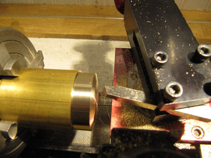
Then moved the chuck back to the lathe to bore out the hole for the crankshaft and the counterbore to take the teeth to face dimension.

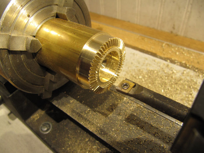
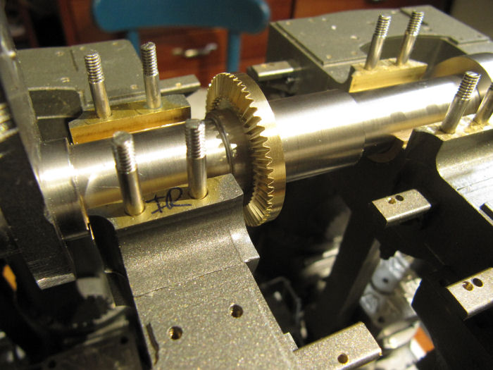
Parted off and test fit on the crankshaft:

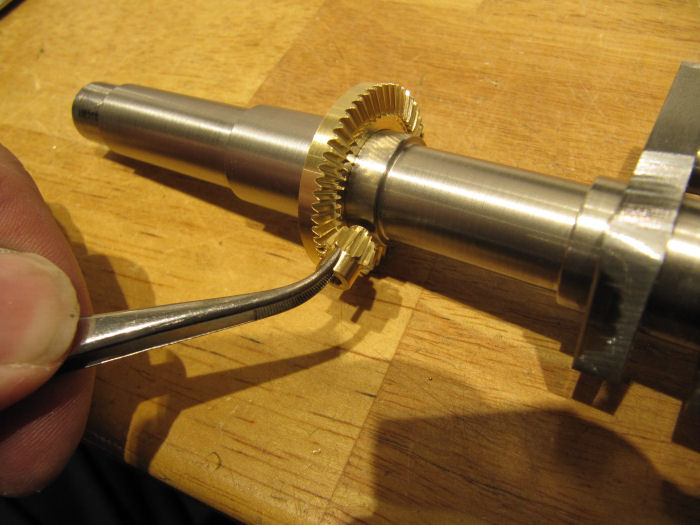
The ring gear will be attached to the flywheel, the pinion gear and its shaft get held by a bearing that will be part of the gear case attached to the engine bed.  Here is where the gear goes when on the rest of the engine:

The drive shaft will come of at an angle to the next level up on the engine frames where the lay shaft will be.
So, three gears down, one to go. The second ring gear has the same number of teeth and outer dimensions, but it will have a smaller hole in its hub to match the lay shaft. Will probably make that gear tomorrow.
 :cheers:

Online Dave Otto

  • Full Member
  • *****
  • Posts: 4704
  • Boise, Idaho USA
    • Photo Bucket
Re: Chris's Holly Pumping Engine Build
« Reply #781 on: July 14, 2021, 10:07:28 PM »
Nice work on the gears Chris, I will have to try that some day.

Dave

Online Kim

  • Global Moderator
  • Full Member
  • *****
  • Posts: 7916
  • Portland, Oregon, USA
Re: Chris's Holly Pumping Engine Build
« Reply #782 on: July 14, 2021, 10:21:29 PM »
Pretty slick gear cutting, Chris!  :popcorn:
Kim

Online crueby

  • Full Member
  • *****
  • Posts: 18665
  • Rochester NY
Re: Chris's Holly Pumping Engine Build
« Reply #783 on: July 14, 2021, 10:25:16 PM »
Thanks guys! Lots of practice has made the gearcutting process a lot faster, the first ones I did years ago took days.

Offline gary.a.ayres

  • Full Member
  • ****
  • Posts: 1297
  • Isle of Skye & sometimes France
Re: Chris's Holly Pumping Engine Build
« Reply #784 on: July 14, 2021, 10:28:17 PM »
Haven't been on the forum much for the last few weeks as busy with my own build and a bunch of other stuff, but now scanning back in your thread I can see amazing progress and a fantastic level of detail.

Offline cnr6400

  • Full Member
  • *****
  • Posts: 2777
Re: Chris's Holly Pumping Engine Build
« Reply #785 on: July 15, 2021, 12:15:25 AM »
 :ThumbsUp: :ThumbsUp: :ThumbsUp: :popcorn: :popcorn: :popcorn:
"I've cut that stock three times, and it's still too short!"

Offline Brian Rupnow

  • Full Member
  • *****
  • Posts: 7606
  • Barrie, Ontario Canada
Re: Chris's Holly Pumping Engine Build
« Reply #786 on: July 15, 2021, 01:52:48 AM »
Chris--I'm not saying much, but I'm setting back in the bush and watching every day. Your work is fabulous!!!---Brian

Online crueby

  • Full Member
  • *****
  • Posts: 18665
  • Rochester NY
Re: Chris's Holly Pumping Engine Build
« Reply #787 on: July 15, 2021, 02:33:23 AM »
Chris--I'm not saying much, but I'm setting back in the bush and watching every day. Your work is fabulous!!!---Brian
Thought I spotted you back there sharing peanuts with the squirrels!  Watch out for the skunk thats started wandering through...
 :cheers:

Online crueby

  • Full Member
  • *****
  • Posts: 18665
  • Rochester NY

Online crueby

  • Full Member
  • *****
  • Posts: 18665
  • Rochester NY
Re: Chris's Holly Pumping Engine Build
« Reply #789 on: July 15, 2021, 04:21:13 PM »
This morning I cut the second large bevel gear, completing the set. With matching gears top and bottom, the lay shaft will rotate at the same speed and in sync with the crankshaft. A nice bit of jewelry that will be unseen under the gear case covers!


Then I got started on putting in the taper pins on the crank pins. The crank pins had been loctited in place yesterday, and the taper pins will give it that extra bit of strength in the joint. The original used tapered keys for the same function. I have bags of 4/0 taper pins in 1/2" and 1" lengths, plus a 4/0 taper reamer. To reduce the amount of reaming needed on the 1" deep holes, I measured every 1/4" on a pin, and worked out a series of drill steps to match, so that all I need to ream off are the corners of the steps on the inside of the holes. On brass, I'd just drill the small hole but on steel this saves a lot of time.

with the reamer run through till the steps are gone, and the oil washed out, the first pin is ready to install.

Here it is after tapping into place, I had put in a drop of loctite just for good measure, though the fit is so tight it probably all squeezed out again.

and after sawing off the ends and filing off

Thats not going anywhere!  So far I have both end crank pins pinned, next up will do the four joints on the center crank - two on the crankshaft ends of the webs and two on the crank pin ends. The joints for the end webs have to wait till the flywheels/gear are installed - positioning the assembly for drilling those will take some supports off the end of the mill table!

Offline derekwarner

  • Full Member
  • ****
  • Posts: 834
  • Wollongong ...... Australia
Re: Chris's Holly Pumping Engine Build
« Reply #790 on: July 16, 2021, 12:17:25 AM »
There is no [modern] engineering joint process that exceeds the accuracy of Tapered Pins  :hammerbash: 

Derek   :cheers:

[mechanical computers used in early Naval Ordinance - Gun Plotting quipment had 100's of minature pinned geared joints [with zero backlash] & all in a box the size of a coffin]
« Last Edit: July 16, 2021, 12:24:16 AM by derekwarner »
Derek L Warner - Honorary Secretary [Retired]
Illawarra Live Steamers Co-op - Australia
www.ils.org.au

Online crueby

  • Full Member
  • *****
  • Posts: 18665
  • Rochester NY
Re: Chris's Holly Pumping Engine Build
« Reply #791 on: July 16, 2021, 02:27:40 AM »
There is no [modern] engineering joint process that exceeds the accuracy of Tapered Pins  :hammerbash: 

Derek   :cheers:

[mechanical computers used in early Naval Ordinance - Gun Plotting quipment had 100's of minature pinned geared joints [with zero backlash] & all in a box the size of a coffin]


They must have some tight control on grinding them, they are amazingly consistent.
I have a couple of WW-II aircraft sextants from bombers, the gears in them are truly amazing, so much packed in a tiny space, as you say without backlash. A long way from the early wood and metal framed sextants in the collection, though they did the job too.


 :cheers:

Online crueby

  • Full Member
  • *****
  • Posts: 18665
  • Rochester NY
Re: Chris's Holly Pumping Engine Build
« Reply #792 on: July 16, 2021, 02:30:02 AM »
Oh, and this afternoon I got the joints on the center crank pinned, and started figuring out how to hold the flywheel castings to mill the hubs. Big darn wheels!

Offline cnr6400

  • Full Member
  • *****
  • Posts: 2777
Re: Chris's Holly Pumping Engine Build
« Reply #793 on: July 16, 2021, 08:56:03 PM »
 :ThumbsUp: :ThumbsUp: :ThumbsUp: :popcorn: :popcorn: :popcorn:

I'm partial to using a plywood faceplate for big flywheels or gears , held in the lathe's 4 jaw chuck. Basically two discs of plywood glued up, the back one small enough to mount in the 4 jaw and the other big enough to fit the item to be screwed to it. If you have the lathe swing, it's cheap and cheerful but it works - IF you don't take massive cuts.  :cheers:

(also spreads the lovely cast iron dust extra far, so a big bonus for black finger club members)  :Lol:
"I've cut that stock three times, and it's still too short!"

Online crueby

  • Full Member
  • *****
  • Posts: 18665
  • Rochester NY
Re: Chris's Holly Pumping Engine Build
« Reply #794 on: July 16, 2021, 09:57:50 PM »
:ThumbsUp: :ThumbsUp: :ThumbsUp: :popcorn: :popcorn: :popcorn:

I'm partial to using a plywood faceplate for big flywheels or gears , held in the lathe's 4 jaw chuck. Basically two discs of plywood glued up, the back one small enough to mount in the 4 jaw and the other big enough to fit the item to be screwed to it. If you have the lathe swing, it's cheap and cheerful but it works - IF you don't take massive cuts.  :cheers:

(also spreads the lovely cast iron dust extra far, so a big bonus for black finger club members)  :Lol:
I've used the plywood discs for some big flywheels, usually bolt them to the faceplate. The headstock thread on the Sherline is the same as some woodworking lathes, and the faceplates made for those can be easily adapted to the Sherline, just needed to trim the thickness around the threaded section. Nice thick steel faceplates a lot cheaper than the thin aluminum ones that come with the lathe.
See next post for how I am holding things!


SimplePortal 2.3.5 © 2008-2012, SimplePortal