Recent Posts
1
Your Own Design / Re: Kearsarge Windlass Engines
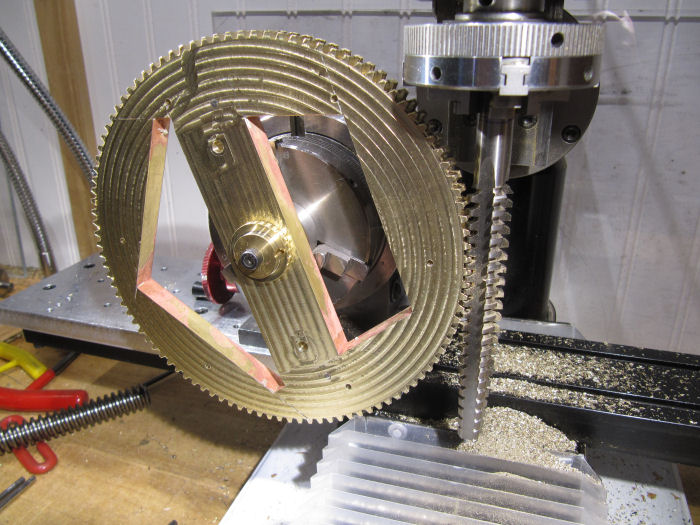
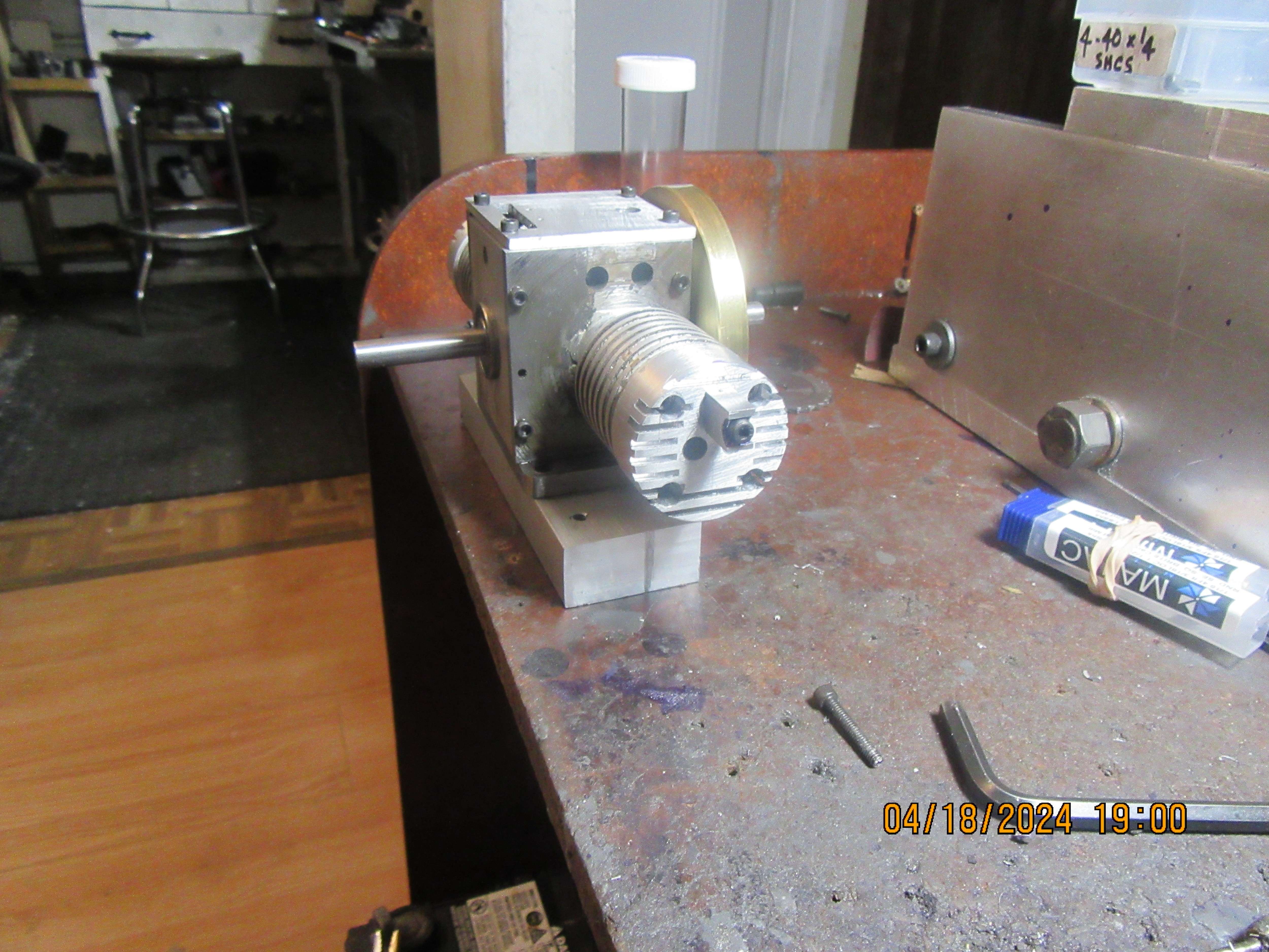
« Last post by steam guy willy on Today at 12:46:41 AM »And today is Hobbing Day! With the gear held in an arbor that lets it spin freely, the Acme tap held in the chuck, it was adjusted till the teeth in the tap meshed with the precut gear teeth, such that if I turned the spindle by hand it would advance the gear without much binding. The cutter was set towards the front slightly, since the blank is over-thick still and the back side will be trimmed off. Started the motor on a slow speed, and started to move the mill table over to start cutting. Every few full turns of the gear the table was moved over another few thou, letting it cut all the way around the gear several times for each position. After a while, got down to full depth.
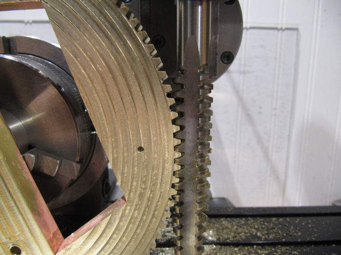
Closer look at the cutter and the tee
Hi Chris , I have allways wanted to cut some gears like this but have never had the need to do it ...did you have to rotate the gear by hand on all the cuts or just the first rotation ?? cool stuff and very satisfying to see it working !!!
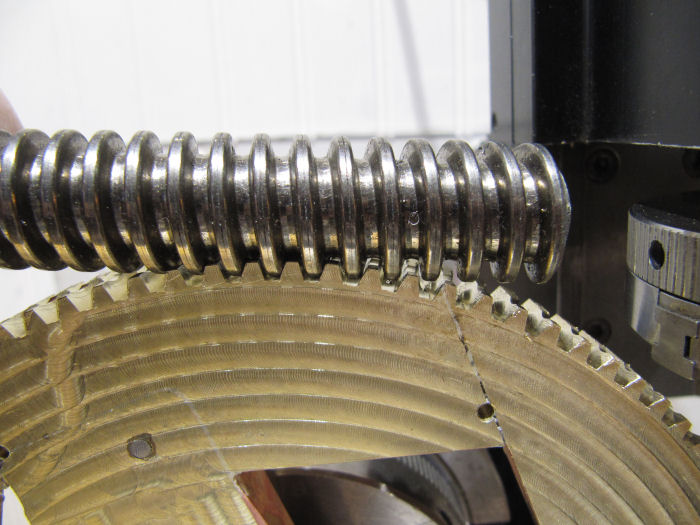
Test fit of the threaded rod on the teeth as I went as well
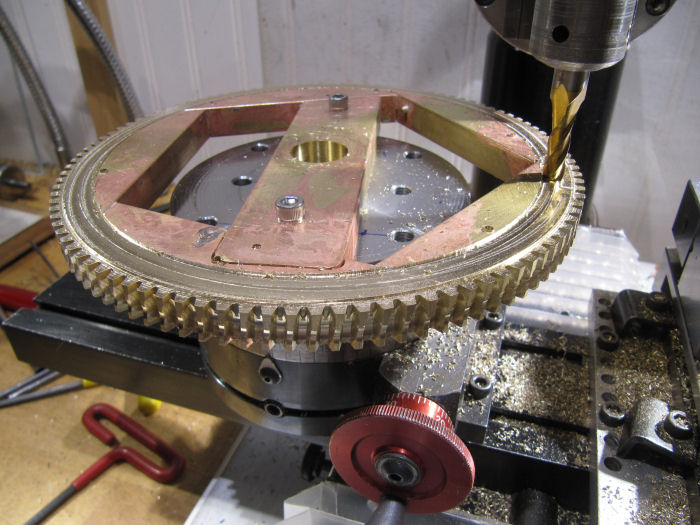
When happy with the depth, it was set down horizontal again to trim off the second side
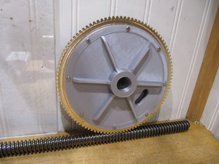
Here is the finished (well almost, need to cut a keyway in the center hole) gear with the side plates screwed on:
This gear is too big for my plating tank, may just paint it instead...