Recent Posts

Pages: 1 ... 4 5 [6] 7 8 ... 10
51
Your Own Design / Re: 5 Cylinder radial somewhat based on the Morton but not much
« Last post by gbritnell on April 21, 2024, 10:53:48 PM »
I cut the aluminum bar stock to the required diameter and cut the step which will later be threaded and the combustion chamber. I center drilled, drilled and used a home-made shaping tool for the combustion chambers. With these steps done it was time to cut the fins. Pucker! Aluminum might be a free cutting material but when it's cutting and the material that you're cutting gets super hot from friction you can get what's known as a pin. This is the same thing you get on a file when the metal sticks to the teeth. You have to constantly lubricate it otherwise the pin can deform, in this case) the thin fin and possibly break the tool. I'm sure many of you have cut aluminum and had it stick to the flutes of your end mill. Not a happy situation.  Anyway I got the heads cut and finned.
52
Your Own Design / Re: 5 Cylinder radial somewhat based on the Morton but not much
« Last post by gbritnell on April 21, 2024, 10:46:30 PM »
The next phase in construction is the cylinders and heads. The heads will be made from aluminum with pressed in steel seats and bronze valve guides. I think when I made the first engine I used continuous cast iron for the cylinders. I don't remember. Not having any material the right diameter I opted to use 1144 stress proof steel. The fins on the heads and cylinder barrels are .035 thick with .040 spaces between. On the cylinders the fins are .200 deep. The first thing was to make a tool. I took a 1/16 thick high speed cut-off blade and ground one end to .04 while trying to maintain draft on the side of the tool.
53
Vehicles & Models / Re: Pennsylvania A3 Switcher (Kozo)
« Last post by MMan on April 21, 2024, 09:10:32 PM »
Hi Kim,

Enjoying this build immensely, if quietly.

For your boiler cutout consider using a hole saw (probably bi-metal for steel) - they are cheap and low on drama if all you want is to remove most of the material and file from there.

All the best,

Martin
54
Your Own Design / Re: 5 Cylinder radial somewhat based on the Morton but not much
« Last post by gbritnell on April 21, 2024, 07:18:30 PM »
Yes there will be a lock nut. Imperial 1-72 thread is .073 diameter (1.85 mm)  In the Metric world  there is a 1.8 x .35 size.
55
Your Own Design / Re: Kearsarge Windlass Engines
« Last post by crueby on April 21, 2024, 06:09:11 PM »
Thanks guys! Its great to see it coming together!   :cheers:
56
Your Own Design / Re: Kearsarge Windlass Engines
« Last post by cnr6400 on April 21, 2024, 06:08:19 PM »
 :ThumbsUp: :ThumbsUp: :ThumbsUp: :popcorn: :popcorn: :popcorn:
57
Your Own Design / Re: Kearsarge Windlass Engines
« Last post by Dave Otto on April 21, 2024, 05:50:29 PM »
Impressive assembly, looks very nice!

Dave
58
Vehicles & Models / Re: Pennsylvania A3 Switcher (Kozo)
« Last post by Kim on April 21, 2024, 05:29:58 PM »
The top of the door does seem to line up with the notch - but the bottom looks a tiny bit above the #37 hole, so you could make it a touch less than 3 9/16" perhaps.

Wilf
This is true, Wilf, and I considered that.
But the bottom of the doors line up exactly with the 3/8" mark for the center of the boiler cut out.  What's weird, is that his 3/8" for the boiler center and the 3/8" for the #37 screw holes don't line up.  So I chalked it up to him doing all his drawings by hand.  Or maybe he was showing that the holes are independent of the boiler center mark and the doors, even though they are shown with the same dimension.  I don't know.  Or maybe he felt that the counter sunk screw holes might interfere with the edge of the door, so he showed them a titch lower to keep them from interfering?  But if that's the case, why didn't he make them a 5/16" or 11/32" or something?  I likely will never know!

Kim
59
Your Own Design / Re: Kearsarge Windlass Engines
« Last post by crueby on April 21, 2024, 05:26:09 PM »
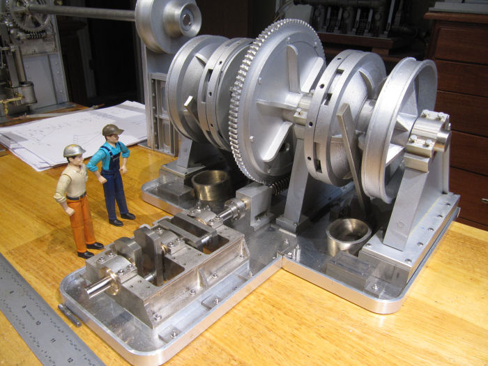
While I was off prepping for the RC submarine run at the pool today, the elves got the flanges installed on the chain drum supports and got them painted too. Here they are after installing them, along with setting the chain guides/pipes in place underneath to mark them for final cutting and installation:

After finishing the chain guides, next up will be to make the ratchet mechanisms for the drums, then the brake bands/control wheels. This picture better shows where this engine assembly will fit inside the rope winches/engine in the background, this engine will be about where the stack of papers is under the rope drum shaft.
60
Your Own Design / Re: Gassie. National Gas Engine
« Last post by Johnmcc69 on April 21, 2024, 09:38:56 AM »
Looks like another good design Jason! That will make for a pretty nice model!

 John
Pages: 1 ... 4 5 [6] 7 8 ... 10
SimplePortal 2.3.5 © 2008-2012, SimplePortal