Recent Posts
1
Your Own Design / Re: Mercedes-Benz W165 Grand Prix engine in 1:3 scale
« Last post by Vixen on Today at 07:42:59 PM »High Pressure Fuel Pump
The next item on the seemingly endless list (I don't expect to be starting another of these epic engine builds, so I had better make this one last) is the high pressure fuel pump, driven off the left hand accessories shaft, outboard of the supercharger scavenge oil pump. The full size W165 engine pumped a toxic mix of methanol, nitro-benzine, acetone and ether into the supercharged engine at high pressure and high flow. The tiny 1.5 litre engine consumed fuel at about 3 or 4 miles per gallon, at full chat.
The fuel pump is a straight forward gear pump. There is an external pressure relief valve to control the fuel pressure delivered to the two carburetors.
I started with the adapter flange which attaches the fuel pump body to the scavenge oil pump. The adapter flange starts life as 30mm diameter aluminium bar stock. The first operation is in lathe, to turn the outside profile and bore the central hole for the bearing. You will notice, I used a 2mm radiused parting tool blade to make the profile cuts. These parting blades willingly cut sideways as well as make plunge cuts; provided the depth of cut is kept small. I machined these profiles using many passes each with the depth of cut increased by 10 thou. All that repetition only takes a few minutes with the CNC and the radiused corners are very pleasing to the eye.

After parting off, the four mounting holes in the scavenge pump flange were drilled to size.

The embryo adapter flange could now be bolted on to a sacrificial jig plate to enable the fuel pump flange to be machined. I picked off the centre of the bearing hole as my datum and machined the square outside profile and drilled and tapped the four mounting holes. The register hole for the second gear shaft was also completed, all at the same datum setting.


The fuel pump body and the outside cover plate were the next items. Both parts were straight forward profile milling operations. Both used same sacrificial jig plate, with four new mounting holes drilled and tapped to match the flange on the previously made adapter.


Here are the three part finished components sitting in line wondering what happens next.

The final (for now) operation on the fuel pump body was to drill and tap and round off the three input/ output bosses. The external pressure relief valve fits above the lone boss on the side. All connection to the fuel pump will be with banjo fittings.


There's more to follow, so stay tuned
Cheers
Mike
The next item on the seemingly endless list (I don't expect to be starting another of these epic engine builds, so I had better make this one last) is the high pressure fuel pump, driven off the left hand accessories shaft, outboard of the supercharger scavenge oil pump. The full size W165 engine pumped a toxic mix of methanol, nitro-benzine, acetone and ether into the supercharged engine at high pressure and high flow. The tiny 1.5 litre engine consumed fuel at about 3 or 4 miles per gallon, at full chat.
The fuel pump is a straight forward gear pump. There is an external pressure relief valve to control the fuel pressure delivered to the two carburetors.
I started with the adapter flange which attaches the fuel pump body to the scavenge oil pump. The adapter flange starts life as 30mm diameter aluminium bar stock. The first operation is in lathe, to turn the outside profile and bore the central hole for the bearing. You will notice, I used a 2mm radiused parting tool blade to make the profile cuts. These parting blades willingly cut sideways as well as make plunge cuts; provided the depth of cut is kept small. I machined these profiles using many passes each with the depth of cut increased by 10 thou. All that repetition only takes a few minutes with the CNC and the radiused corners are very pleasing to the eye.
After parting off, the four mounting holes in the scavenge pump flange were drilled to size.
The embryo adapter flange could now be bolted on to a sacrificial jig plate to enable the fuel pump flange to be machined. I picked off the centre of the bearing hole as my datum and machined the square outside profile and drilled and tapped the four mounting holes. The register hole for the second gear shaft was also completed, all at the same datum setting.
The fuel pump body and the outside cover plate were the next items. Both parts were straight forward profile milling operations. Both used same sacrificial jig plate, with four new mounting holes drilled and tapped to match the flange on the previously made adapter.
Here are the three part finished components sitting in line wondering what happens next.
The final (for now) operation on the fuel pump body was to drill and tap and round off the three input/ output bosses. The external pressure relief valve fits above the lone boss on the side. All connection to the fuel pump will be with banjo fittings.
There's more to follow, so stay tuned
Cheers
Mike


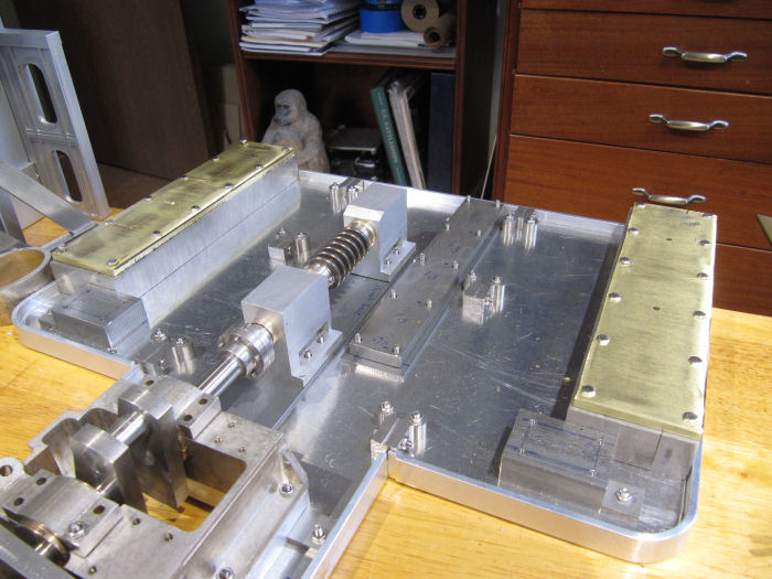
 Did get them finished up, here are all three set in place on the main base plate - the two brass ones at the sides, the steel one in the middle.