Recent Posts

Pages: [1] 2 3 ... 10
1
Woa - just as I thought - you had to bring the latest parts up to the same standard as the rest  :praise2:

I'm usually not bothered much about Nuts as long as they do their job, don't corrode or look really bad .... But I do get why it matters when you try to achive an exact replica of the original - so yes the last pic has the best match  :ThumbsUp:

Argh  :zap: - Yes that is annoying .... But you can usually still get Discrete Parts that will do the job just as well as the original ones today - though they might be in a 'Different Package' ....

I Hope the repair isn't expensive nor take long to fix ....

Per      :cheers:
2
Your Own Design / Re: Kearsarge Windlass Engines
« Last post by cnr6400 on Today at 04:24:58 PM »
 :ThumbsUp: :ThumbsUp: :ThumbsUp: :popcorn: :popcorn: :popcorn:
3
Your Own Design / Re: Kearsarge Windlass Engines
« Last post by crueby on Today at 03:41:59 PM »
The bearing block pieces were all trimmed to length then bolted together to bore the shaft holes...

Then both sides trimmed back to final dimensions

The caps had the ends stepped in

and rounded off

Here are the two end ones slipped onto the shaft, with the vertical walls set behind them

Since the positions are sensitive to any variation in the angles/heights of the walls and OD of the gears, I'll get things positioned so the gear meshes well, and mark the blocks/walls to drill the final mounting holes in them as well as between the walls and the base plates. That should give a better fit than just using the original plan dimensions - lots of tolerances stacked up here! After the end walls/bearings are locked down, then I'll do the middle one and its bearing, which sits next to the gear.
4
Your Own Design / Re: Junkers CLM
« Last post by Vixen on Today at 12:56:14 PM »
Hello Roger,

Very long and slender 'Pull' rods. Nice transition from shaft to the bearing eye.  :ThumbsUp: :ThumbsUp:

It looks like you had to hold the square shaft in a round collet? Any problems with the corners interfering with the collet's slits?

Mike
5
Your Own Design / Re: Mercedes-Benz W165 Grand Prix engine in 1:3 scale
« Last post by Vixen on Today at 12:39:30 PM »
Thank you Roger and Per,

You both make a good point about the use of that fuel pump on the model engine. The full size pump, which I am copying in 1/3 scale, was sized to provide more than enough fuel for 300 HP at 8,000 RPM. Even when scaled down, the model pump will still provide fuel well in excesses of my requirements. The output of a gear pump is proportional to speed, so some form of regulator is required to control (overflow) the excess fuel sent back to the tank.

I will be using diaphragm 'float chambers' which are best suited to gravity feed, as opposed to pumped feed. I expect to use a gravity tank on the model, for simplicity. Actually, I have a choice of two fuel feed options. The racing car did not have both options, it needs to pump the fuel from car's fuel tanks, situated in the tail and over the drivers lap.

Just for you Per, I did some more fetling on the pumps.  :stir:     
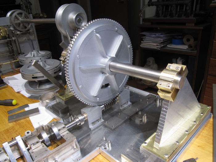
Here you can see one assembled (less the gears). Standard M2.5 nuts are big and do not look quite right, so I tried some of the commercially available under-size M2.5 miniature nuts (on the left). I did not like their look either. I resorted to drilling and tapping standard M2 nuts. You can see those of the right, to my eyes they look much more realistic.


This is the fuel pump mounted on the engine, outboard of the supercharger scavenge pump. Mercedes Benz may have produced some of the most powerful race engines, but the snake pit of external pipe work was a mess, almost as bad as the tangle of oil pipework in the dry sump.


Now that all the accessories on the left side are complete and in place, I now know what space they want to occupy and can now try to bend the external copper coolant pipe to fit correctly.

I was about to make a start on the banjo fittings and the pump gears. When I switched on the lathe yesterday, it went phut  :zap: and refused to start. I suspect it is the main PSU at fault. The PSU is over 40 years old, it's all discrete components, transformer, rectifiers and capacitors etc. so relatively easy to fault find and fix, assuming I can still buy the components.

One step forward and one step back. Patience !!!!

Cheers   :cheers:

Mike

6
Chatterbox / Re: Still working on it
« Last post by crueby on Today at 12:37:30 PM »
Larger valves and ports are fine, they would give the best range of speeds. What I find works great is to have a needle type throttle valve close in on the steam line. That restricts flow even at full boiler pressure, to give you best speed control.
7
Great to see progress again Mike  :ThumbsUp:

I'm guessing that the parts needs a bit more fetling (sp?).

Rogers question makes sense - if you do use it - will it require an 'overflow system' ?

Per        :cheers:
8
Your Own Design / Re: Junkers CLM
« Last post by Admiral_dk on Today at 09:45:22 AM »
Glad that you have planed for it all and the result looks good  :ThumbsUp:

Per           :cheers:
9
Vehicles & Models / Re: Pennsylvania A3 Switcher (Kozo)
« Last post by Roger B on Today at 08:21:32 AM »
Kozo certainly gives you some fun fabrications  :ThumbsUp:  :ThumbsUp: Coming along nicely  :)  :wine1:
10
Your Own Design / Re: Junkers CLM
« Last post by Roger B on Today at 08:06:25 AM »
The second rod was finished in the same way and I started cleaning then up. There are some machining marks on the shaft where the two turning operations met that I will have to polish out although there is not much bending stress at that end of the rod mostly tension when the engine is running.
Pages: [1] 2 3 ... 10
SimplePortal 2.3.5 © 2008-2012, SimplePortal