Hi all,
As I mentioned over in my Mann Wagon build, I took time out to redo the handwheel assemblies at the ends of the leadscrews on my Sherline lathe and mill. The way Sherline makes them, they depend on a little set screw in the side of the handwheel to grip onto the end of the leadscrew shaft, and the position of the handwheel controls the amount of lash in the table movement. Problem is, that there is no way to adjust the position other than pushing it into place and tightening the set screw, which can shift slightly on the shaft. Also, they have steel on steel surfaces, which wear over time, and if the setscrew slips on the shaft there can be lots of lash, which is nasty when milling. Sherline does make a CNC version of the leadscrew assembly, which has ball bearings and a preload adjusting nut. However, I found that the bearings they used, which are not thrust bearings, dont hold up over time (I use my lathe and mill a LOT) and the preload nut has a tendancy to back out from time to time.
So, having been frustrated with dealing with getting large amounts (10 to 15 thou) of lash appearing from time to time, which can cause chatter, shifting of the table, and sometimes breaking a small end mill, I've finally come up with a design that uses off the shelf thrust bearings, and is giving me less than a thou of lash while moving smoothly. For the thrust bearings, I got some S51100 stainless grooved washer bearings from Bearings Direct - here is the link, though over time the path may change:
https://bearingsdirect.com/ball-bearings/thrust-ball-bearing-single-row/thrust-ball-bearings-3-piece/51100-series/51100-single-row-thrust-ball-bearing-id-10-x-od-24-x-w-9mm-groovedThese are rated for a very high load, probably overkill for this use, but the smaller ones I found had pretty light ratings. Using them, I designed up a holder that will slip onto the existing leadscrew end (I filed a flat for the setscrew to grip to best) while using the existing handwheels. It consists of an extension to the leadscrew end, which holds two thrust bearings either side of a central plate, with a round housing that bolts onto the end of the table. The newer Sherlines come with the holes for their CNC adapter already drilled, so if you have an older unit you will have to drill/tap those holes - sherline does have a drilling guide they sell, though it is easy enough to make your own to match the housing in the plans. Here is a photo of one completed unit installed on my mill, with a second one sitting apart below on the table:
Nothing about it is complex to make. I used 303 stainless steel for the parts, plus a bit of bearing bronze for the cover plate where the shaft comes out.
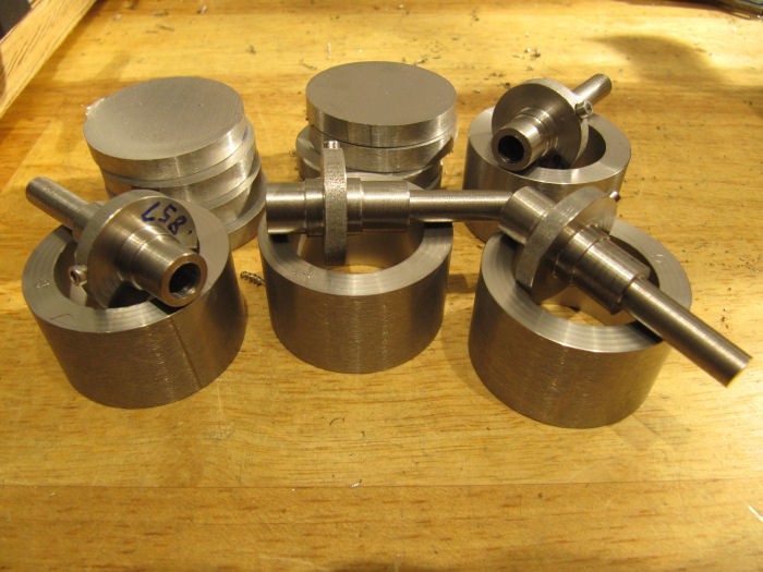
Starting with the shaft extension, the outer end was turned into a bar, then the bar turned around and the inner end was turned to match. Note that there is a step near the inside corner, these bearings have a larger hole in one washer, so this was turned in a a close fit to the washer.
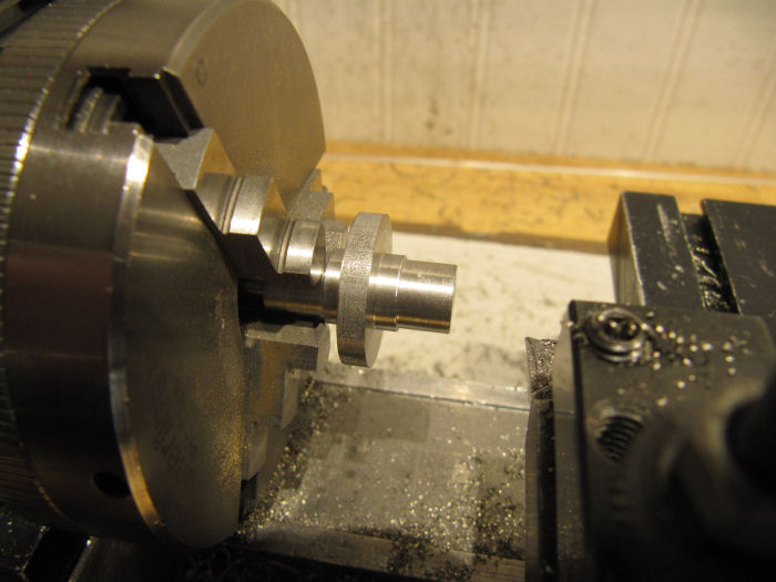
The thickness of the center plate is not critical, but its easiest to make all the same. Later that will be measured and the housing adjusted to it. Here is one of the bearing sets test fit on the end of the shaft - you want the inner washer to rest flat against the center plate.
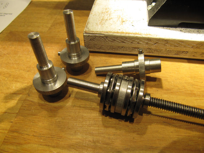
Four total were turned up, to do the X/Y axis on both the lathe and mill. The Z axis on the mill already has a thrust bearing with tension adjustment (why didn't they do that on all from the factory? ). There is a set screw through the center plates, 2-56, which holds the existing end of the leadscrew shaft. I filed a flat on the shaft for best hold.
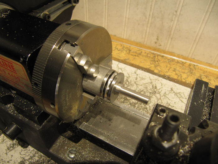
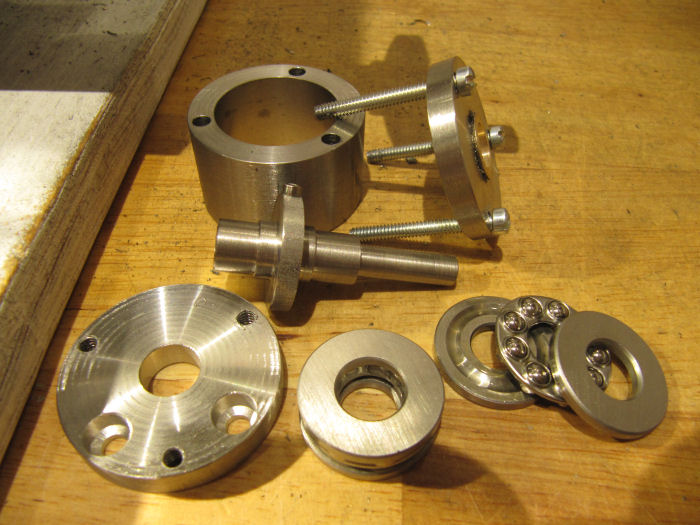
Then turned the housings and end plates. The thickness of the plates is not critical, but the length of the housing IS. To get no lash, you want the length of the housing to match the total distance end to end of the washers when the bearings are assembled on the shafts. So, I measured each set, and made a note on each one so I could get a match, and kept each set together. That way, when the cover plates are screwed on, they preload and hold the bearings in place. This photo shows them before drilling the mounting holes. The inner bore of the covers is not a bearing surface, it just needs to clear the bearings and set screw.
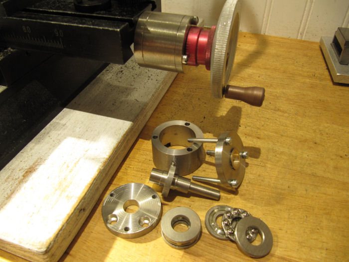
Here are all the parts for a unit ready to assemble. I test fit, then took it apart again to add grease to the bearing races.
The two countersunk holes in the base plate are to take the screws that hold them to the frame of the machine. Here is the first one installed and working well. On the mill table is a thick black washer - that it the holder for the end of the shaft as built in the factory, one screw and it comes off. The handwheel I put on is a larger diameter one I made from aluminum, using the original zero-reset scale tube.
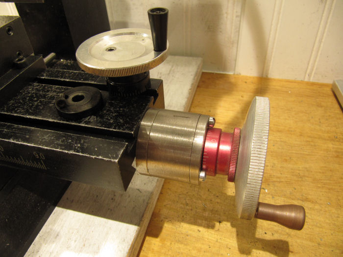
Thats it - all the parts can be assembly-line made to get the sets for each machine. I currently have both installed on the mill, and one installed on the lathe cross slide. The long-axis end of my lathe did not come drilled since it is an older model, I need to drill/tap that to install the last one.
Hope this comes in handy for anyone with a Sherline, plans are attached to this post.
Chris


