Right I will try and explain how I done the cam, please note `I am not a CAD hero`, I normally just use a a pencil(old school you see). There are probably far easier and quicker ways to get to the required end result, but this is how I figured out how to do it.
If we have to make a cam with a large diameter of say 20mm and a tip radius of 6mm, the distance between the centres of these is 10mm. One flank has a radius of 30mm and the other a flank of 35mm.
In your favourite cad package draw a circle of 20mm dia.
Next draw another circle of 12mm dia.
Position these circle centres at 10mm apart. You should now have the two circles positioned the correct distance apart.
Next I draw a circle with a diameter of 60mm. I then move this circle to position it so that it intersects the sides of the circles already drawn.
Draw another circle of 70mm diameter and move this to intersect the first two circles on the other side.
I then use the trim function to trim all the unwanted lines to leave the profile of the cam required.
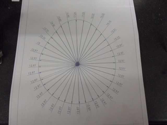
Draw a line from the centre of the first circle, well out past the radius of this circle.
Use the radial array function to equally space 36 of these lines about the centre of the first circle.
Once again trim these lines to the outside profile of the cam you have drawn.
You can then use the dimension tool to give you the length of each line.
This is what I end up with.
Hope you can follow this, I`m not very good explaining things on screen

Once this is done, I make up a blank slightly larger than the biggest radius then mount in the RT and plunge cut to the desired depth from the centre. The cam is then removed and the peaks filed down to the base of the troughs and that should be it, a nice cam.
Roger has pointed out a couple of good points above and i will try them out next time, thanks Roger.
Cheers,
MartinH


