Bill, John, Thomas, Brian, Dave, Chris, bent, Flopearedmule; thanks for your compliments and feedback. Thanks again for the others stopping by from time to time to see my progress.
I got back from the Cabin Fever Expo (had a GREAT time) just in time for some abnormally cold weather; I also had some chores to do, so I didnt get back in the shop till today.
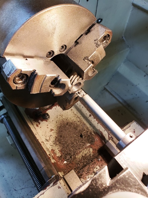
First on the agenda was boring the supplied gears to accept the engine shafts. Here Im boring the crankshaft gear.
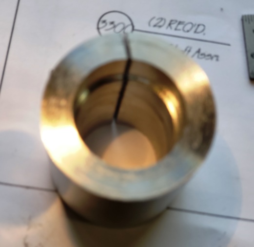
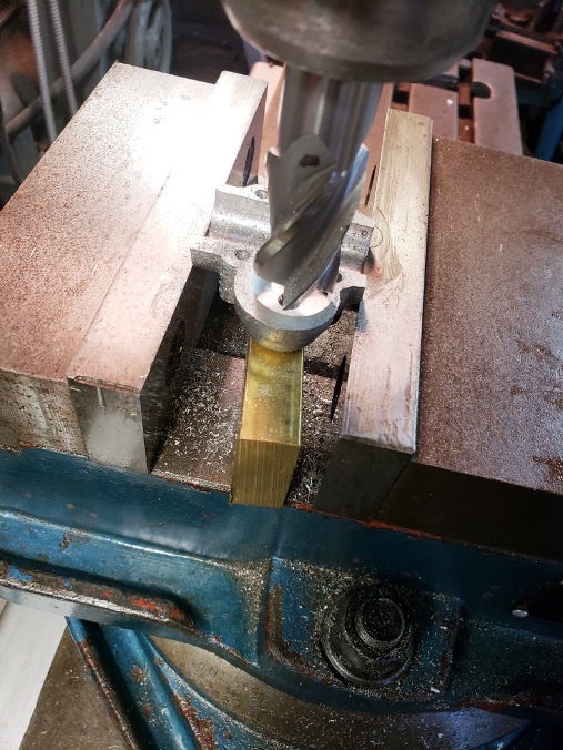
The helical angle on the camshaft gear is much less than that on the crankshaft gears. The gear didnt seem to mount well in the 3-jaw chuck so I decided to make a fixture to hold it. This is the fixture. It has a shoulder which the gear rests upon and is slit so that the lathe chuck will compress the fixture and grip the gear. This is the fixture (sorry for the blurry picture)
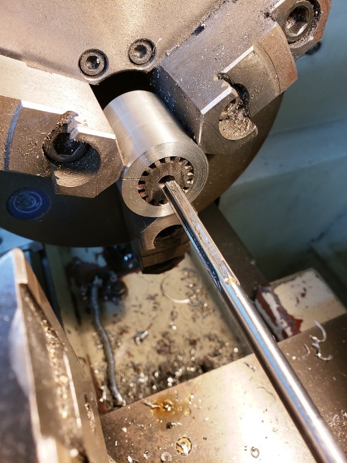
And here is the fixture and gear mounted in the lathe.

Here Ive center drilled the gear, drilled the center, and am reaming the final diameter of ¼ inch. The drawings dont describe how this gear is attached to the camshaft (there is no keyway as with the crankshaft gear). Im thinking a press fit or just Locktite it to the shaft. Any thoughts?

I thought I took a photo of the operation of clearing space for the camshaft gear. I guess I didnt because there wasnt one on the camera.

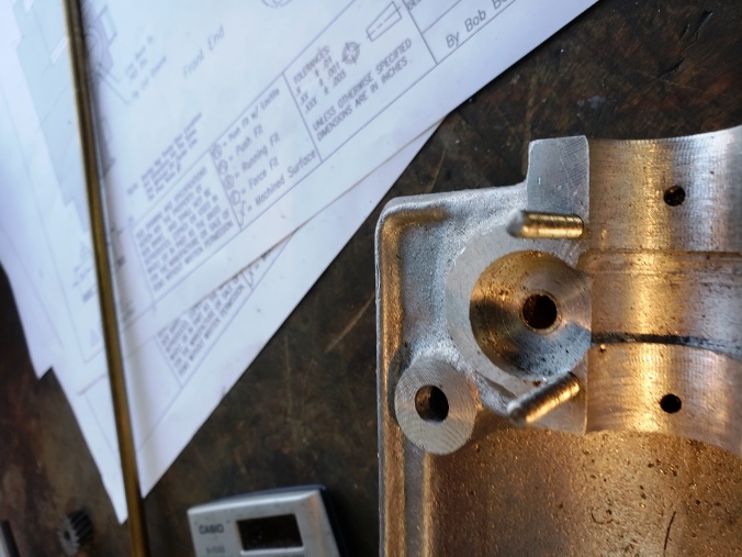
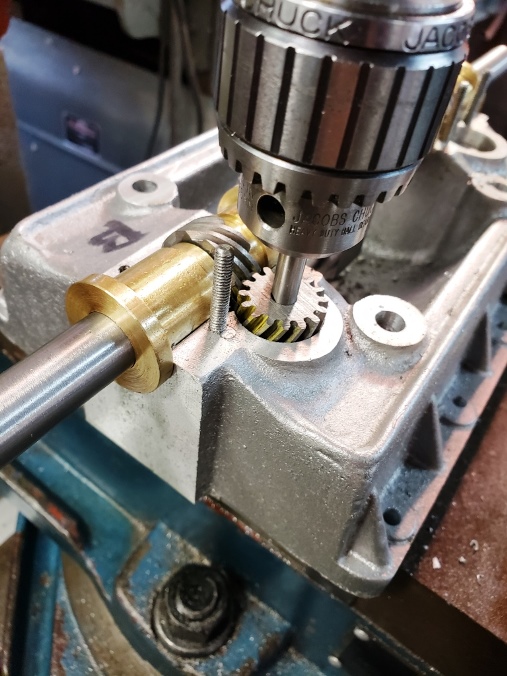
In this photo Im fitting the gear. The building notes indicate you should spot the hole for the lower bearing (there was no measurement given). I did this by mounting the engine base to my mill, assembling the gear train, then rotating the crankshaft and letting the cam gear rotate on this drill center. I moved the mill table in and out till the gear ran freely with little backlash. This gave me the location to drill for the bottom bearing hole. I zeroed the DRO on my mill to this location using the ABS index for the one camshaft and the INC index for the other. This allowed me to relocate both these centers.
Once the holes for the bottom bearings were drilled in the base, I attached the gear covers and center drilled, drilled, and reamed both gear covers using the pre-established DRO zero described above.
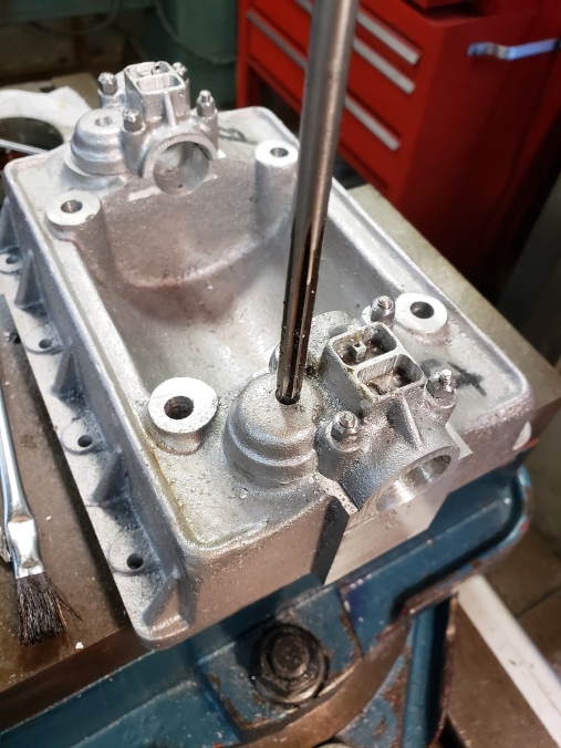
With the gear covers drilled through, I could invert them in the mill vice, center on the hole, then mill clearance for the gear in the gear cover. The building notes indicate that there is very little clearance and there is a risk of breaking through the casting in this operation. I achieved the measurements given without a breakout.

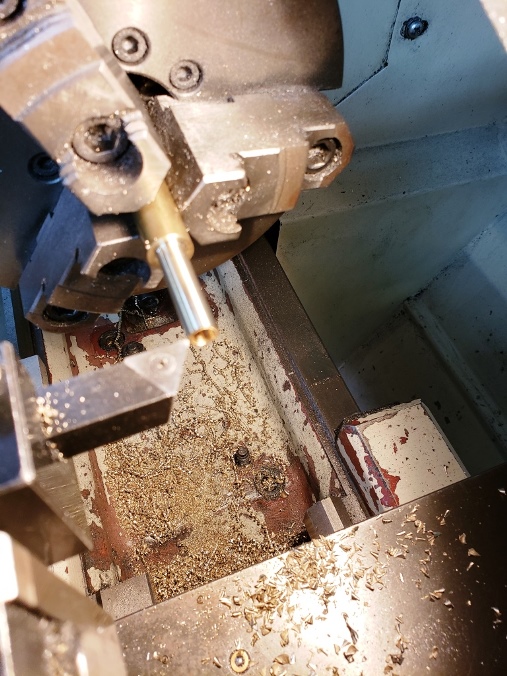
The drawings call for the steel camshaft to fit into a reamed hole in the engine base. With the engine base being aluminum I just couldnt envision where an aluminum bearing would suffice. Im sure it probably works ok but I decided to oversize the hole and use a brass bearing instead. Here Im fabricating the bearing. Im using my new Arthur R Warner tooling I acquired at the Cabin Fever Expo. I wanted to get some carbide tooling for turning flywheels and I kept walking by the Warner tooling booth and drooling; I finally bit. The tooling comes standard with HSS inserts. I also got some carbide inserts for the flywheels.
Hard to see but here Ive pressed the bearing into the engine base. All ready to receive the ¼ inch camshaft.