Author Topic: Squint Scale Curtiss Model K Aero I4  (Read 18153 times)

Offline RReid

  • Full Member
  • ****
  • Posts: 1697
  • Northern California
Re: Squint Scale Curtiss Model K Aero I4
« Reply #255 on: April 13, 2024, 12:57:47 AM »
Thank you Bent! :cheers:
Regards,
Ron

Offline Roger B

  • Global Moderator
  • Full Member
  • *****
  • Posts: 6162
  • Switzerland
Re: Squint Scale Curtiss Model K Aero I4
« Reply #256 on: April 13, 2024, 07:55:59 AM »
Looking good  :praise2:  Nearly there  :ThumbsUp:  :wine1:
Best regards

Roger

Offline RReid

  • Full Member
  • ****
  • Posts: 1697
  • Northern California
Re: Squint Scale Curtiss Model K Aero I4
« Reply #257 on: April 14, 2024, 01:11:00 AM »
Thanks Roger! :wine1:

Working on a number of loose ends. Remade the "horseshoe magnet" of the magneto for a better, more prototypical appearance. Also made up some discs for Hall effect magnets. One for the crankshaft gear, one for the magneto drive gear. A third option for a magnet location is the cam gear, which has a large enough OD to not need a separate disc. The plan is to use two TIM-6 ignition modules and two Hall effect triggers, one firing cylinders 1 & 4, the other firing 2 & 3 in a wasted spark configuration. Finally, a mounting bar for the dummy water pump. Some pictures next time.
Regards,
Ron

Offline scc

  • Full Member
  • ****
  • Posts: 1107
  • Lancashire, UK
Re: Squint Scale Curtiss Model K Aero I4
« Reply #258 on: April 14, 2024, 09:10:07 PM »
NICE       :ThumbsUp:     Terry

Offline RReid

  • Full Member
  • ****
  • Posts: 1697
  • Northern California
Re: Squint Scale Curtiss Model K Aero I4
« Reply #259 on: April 15, 2024, 01:02:44 AM »
Thanks Terry! :cheers:

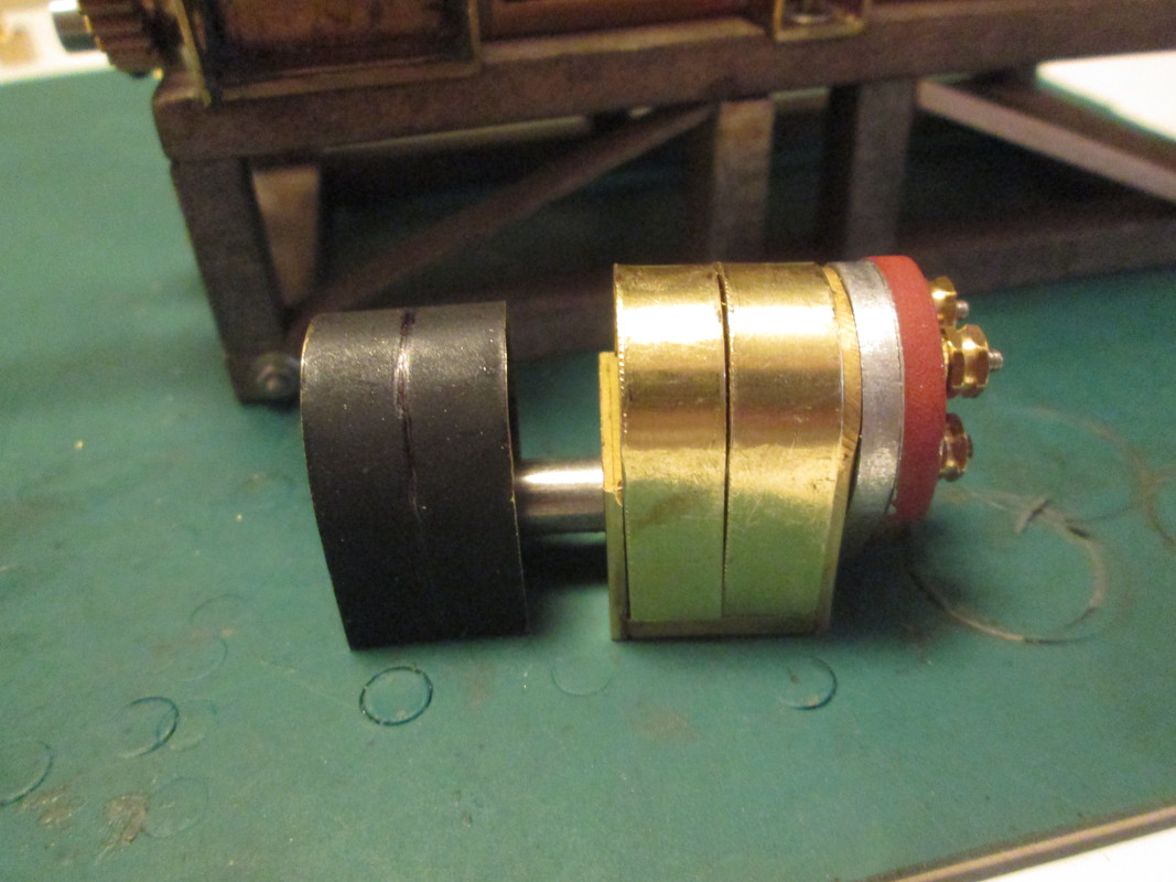
Here are the pictures I promised in the last post. Below is the original “horseshoe magnet”, and next to it the unpainted new version. Those early magnetos actually have two magnets mounted side by side. Since I thought it would work better to bend one piece rather than two (and hope they come out the same), and I didn't think that trying to make a cut after bending would work out well, I tried to simulate the gap between with a scribed line and and different shade of black to suggest the shadow in the gap. The bending worked well, the visual trickery not so much. Then it occurred to me that, since the back of the part is basically invisible, I could make a cut up the middle of the blank only part way, then do the bending. This worked well and looks much more convincing.


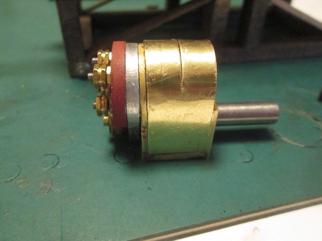
Here's the back side, showing how the cut stops short. I used aviation snips to make the cut. A razor saw would also work, but the blade in mine is toast. Needs to be but hasn't yet been replaced.


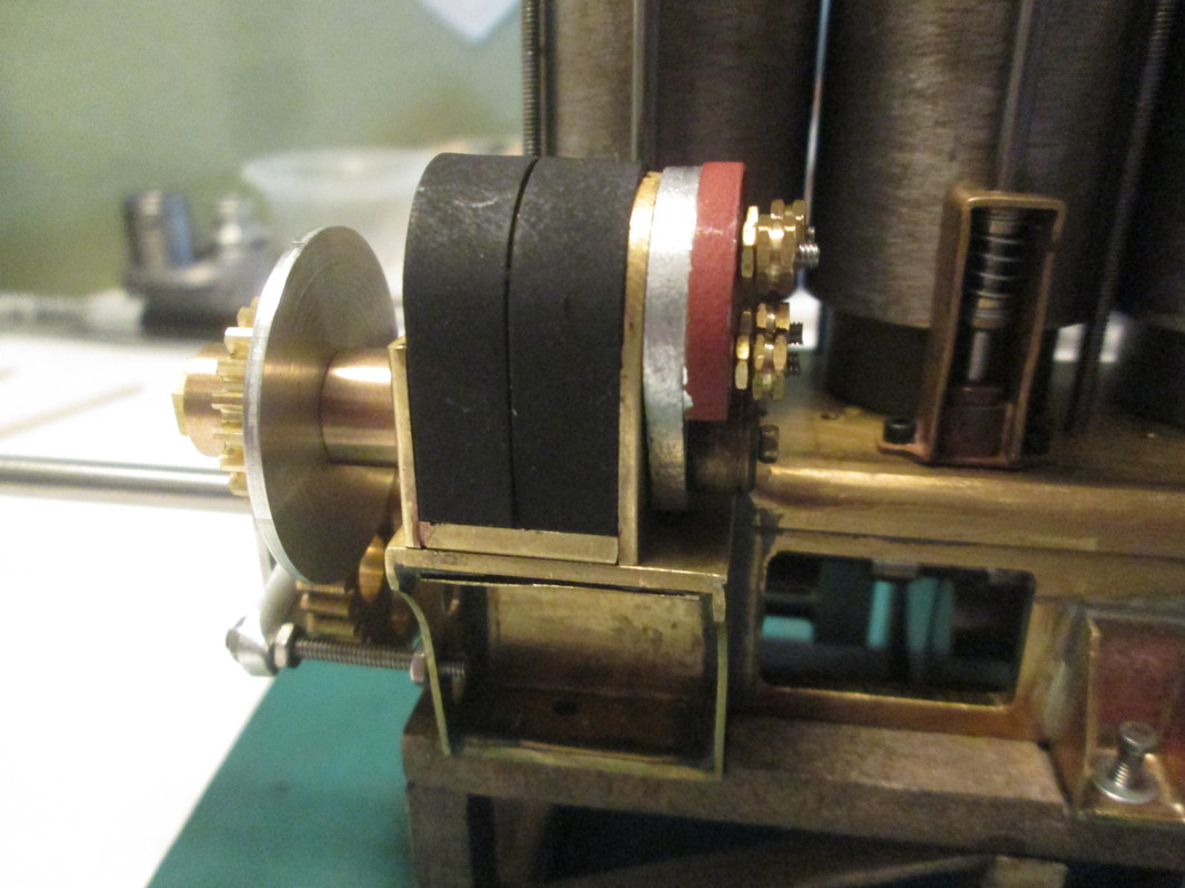
Painted and in place.


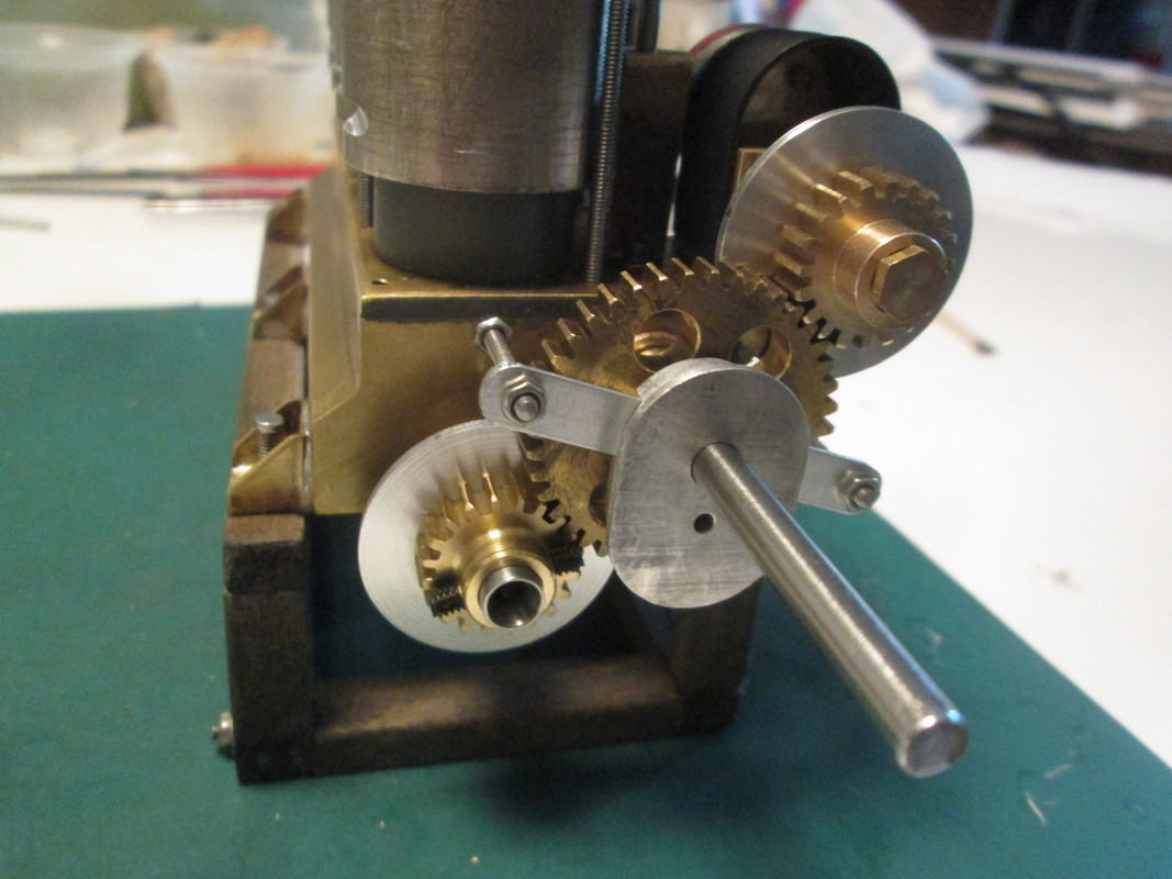
This last photo shows the two ali disks, behind each of the smaller gears, which will carry a Hall effect magnet for the ignition system.

Also shown is the “water pump”, which is due to get a bit more work for appearances sake. The mounting bar for it functions also to limit the movement of the camshaft in that direction. The cam bearing at that end of the crankcase is flanged, but the flange is on the outside so that it can be pulled out, allowing for the removal of the entire camshaft. Originally I had thought to fix that bearing in place with a set screw, but using the mounting bar serves the same purpose more simply. I also need to order some shorter set screws for the gears!

Regards,
Ron


SimplePortal 2.3.5 © 2008-2012, SimplePortal