Thanks Gary, with a bit of luck it will be chuffing away shortly

My main computer finally packed up after about 6 years of hard labour so I did have a few days with only my tablet which isn't great for taking images, but now armed with my new sooper dooper Windows whateveritis computer I have now been able to upload a few images from my camera showing the progress so far.
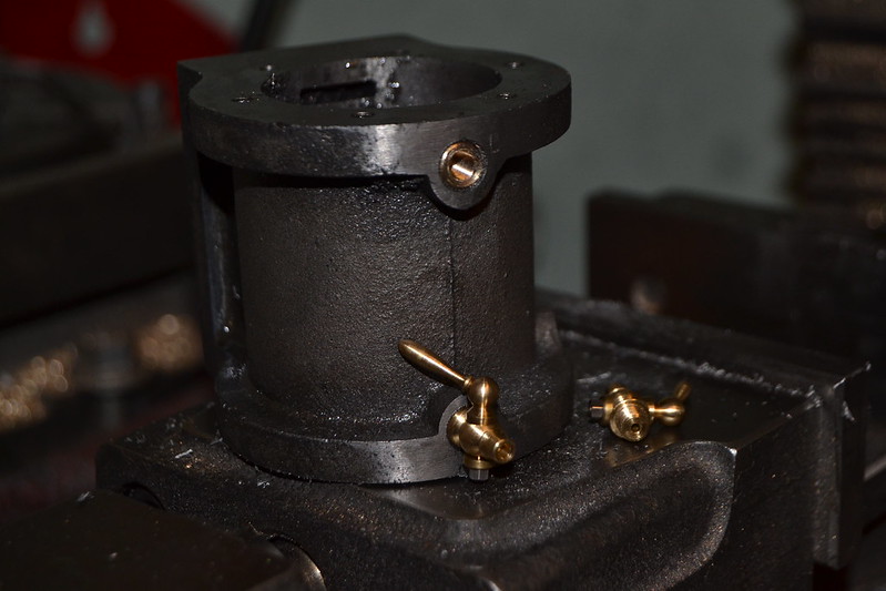
Firstly I decided to fit the new drain cocks, the intention is to run this engine on the hot stuff so it made sense to fit drain cocks. With M5 fine threads I found that tapping into cast iron wasn't a great success so I opted for fitting threaded brass sleeves first.
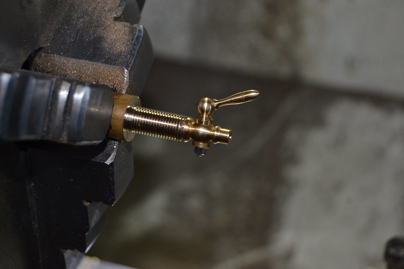
With the cylinder threaded they add a nice little touch and I'm pleased with the look. They may need a bit of shimming to get them both upright and parallel but I'll deal with that at the cladding stage.
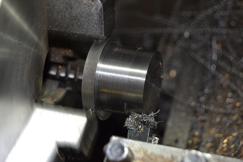
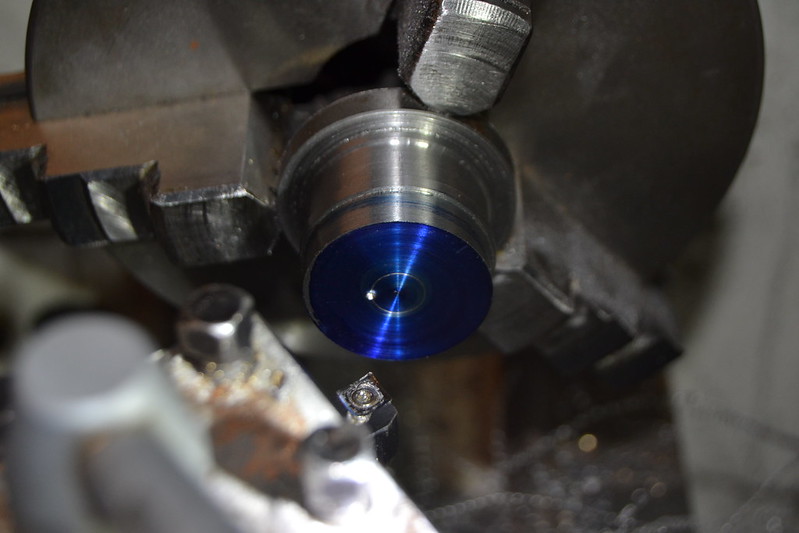
Making the eccentric seemed to be the obvious next step so it's time to turn down a piece of steel that will form the sheave. I did wonder about making this from brass and making a steel eccentric strap but settled on the opposite, so steel it is...
Another area I pondered over was how to 'captivate' the strap on the eccentric, I thought it may be easier to cut a groove in the sheave and turn the strap with a raised internal diameter to match but having looked at other engines it seems it is more usual to have the groove in the strap and the raised 'ridge' in the sheave so I thought I'd give it a try.
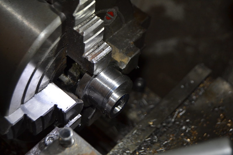
Here I'm starting to turn the sheave diameter but leaving the 'ridge'. The plans call for this to be
1 /
32" high which doesn't seem a lot to me but I'll stick with that.
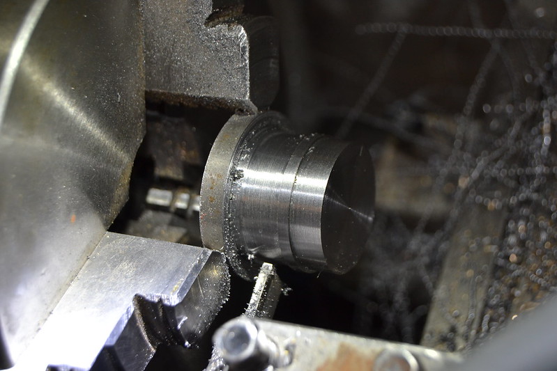
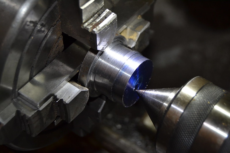
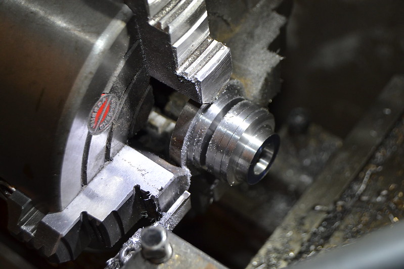
With the outer diameter successfully turned I need to now work on the
5/
32" throw so the crossslide is set at the required radius allowing the tool to scribe a line, a centre punch marks the spot
With the part now sitting on parallels in the 4 jaw its a simple job to line the punch mark up with a tailstock centre to obtain the required offset.
Drilling and reaming to 12mm for the crankshaft.
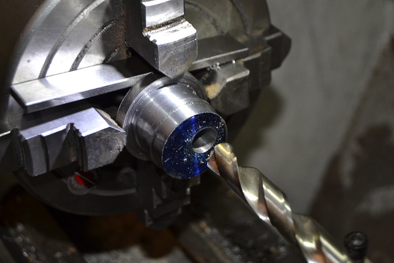
I hadn't noticed until now but it looks suspiciously like I may have left a parallel in the chuck while turning the boss

Anyway I got away with that one

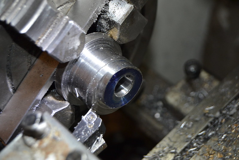
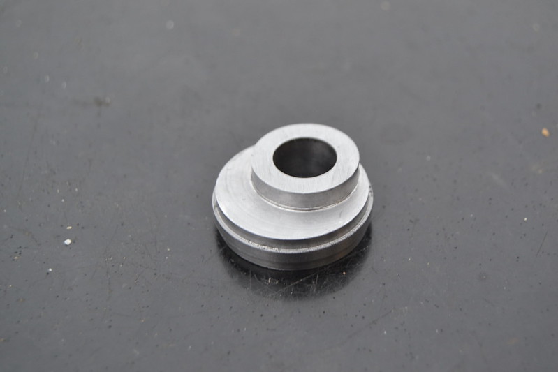
Kinda looks like and eccentric sheave, so time to part it off.
Parting off with an offset workpiece probably isn't a good idea but with a sharp tool it works fine.
So far so good...
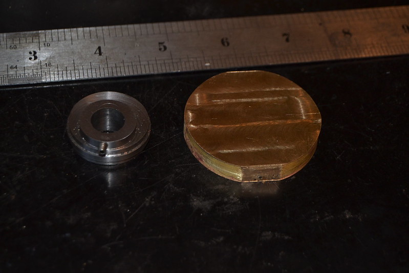
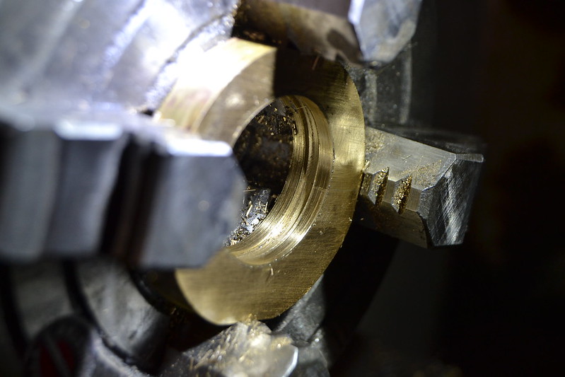
With the sheave tapped at 3mm for a grub screw it time to look at the eccentric strap. A disc of scrap brass about 9mm thick looks just about big enough for what I need, I'm not too worried about the outer profile being exactly as the Stuart drawing suggests as long as the finished item looks appropriate in scale, shape etc. Here it has been hacksawed in half then silver soldered back together for machining. A small flat on each side was milled to help holding in the 4 jaw and aid profiling later.
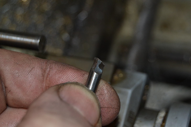
Before mounting the strap in the chuck for boring I thought it worthwhile making a tool to cut the internal groove and testing how it performed. Broken centre drills are a readily available item for most beginners and they make useful blanks when it comes to making one off tools.
This little fella is a bit rough and ready but ought to manage a small groove in a piece of brass.
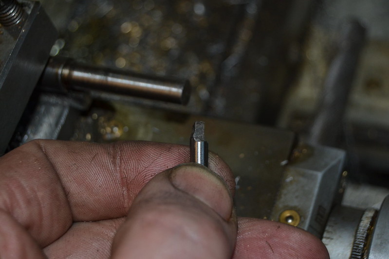
With a simple holder made it seems to cut external grooves ok at the correct size for the eccentric.
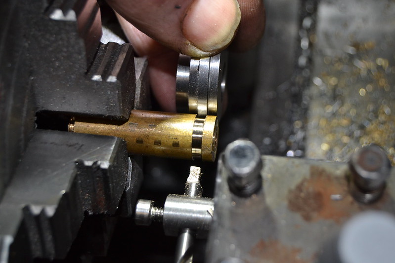
The strap is drilled then bored to be a close fit on the main body of the sheave.
This photo isn't great but here I am ready to plunge in on the far side and (hopefully) end up with a neat groove. I chose to cut away from the camera with the lathe in reverse largely because it was easier to see what was happening but I guess it's not really important either way.
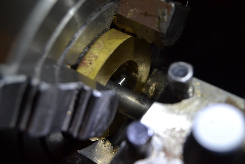
It seems to have done the job
There is a hint of chatter on the bottom surface of the groove but it is small and that area shouldn't be a contact / running area.
Quite happy with that...
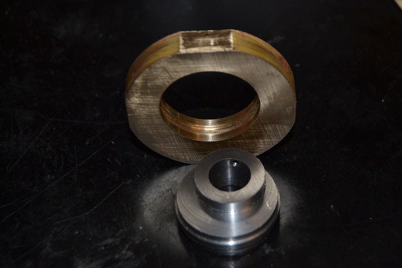
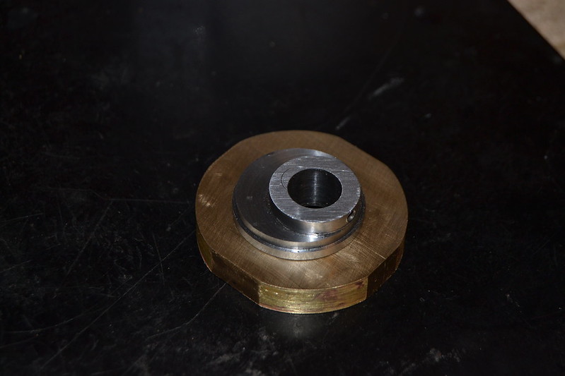
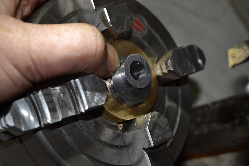
I'm not yet sure how well the strap will fit until I've profiled it then split it to assemble over the sheave but I'm cautiously optimistic.
The next stage after finishing the eccentric assembly will be to make the rod leading to the valve rod, I could do with a bit of advice here if anyone can help. The eccentric sheave will sit outside the line of the valve rod, it's only small (perhaps 3mm) but does mean I'll have to incorporate a 'dogleg' in the eccentric rod

I had initially planned on the rod being a tapered flat bar but now that I need to add an offset I'm thinking a round rod about 5mm dia may be a better option. Anyone got any advice how to create accurate 'dog legs'? Will heating the steel help? I'd be grateful for any advice
With a bit of luck I'll have it running in a few days


