Author Topic: Little and large - building 2 vertical steam engines.  (Read 29894 times)

Offline Jasonb

  • Full Member
  • *****
  • Posts: 9487
  • Surrey, UK
Re: Little and large - building 2 vertical steam engines.
« Reply #180 on: June 22, 2018, 02:37:00 PM »
Or just drill 3/4" at each end and then use a smaller cutter to do the sides of the slot.

Boring head is best done with a series of plunge cuts rather than trying to move the work against the spinning cutter

Offline Gas_mantle

  • Full Member
  • ****
  • Posts: 1365
  • North Yorks - UK.
    • My Youtube channel
Re: Little and large - building 2 vertical steam engines.
« Reply #181 on: June 22, 2018, 02:49:51 PM »
Thanks Jason,

I was kinda thinking of opening out drilled holes at either end of the slot with the boring head then just use a standard milling cutter to link them.

Now that John has offered suggestions  it's pretty obvious to see there are numerous ways to achieve the desired result but it's something I'd never really thought about till now and with boring head getting little use I overlooked it completely  :headscratch:

Offline gary.a.ayres

  • Full Member
  • ****
  • Posts: 1297
  • Isle of Skye & sometimes France
Re: Little and large - building 2 vertical steam engines.
« Reply #182 on: July 04, 2018, 12:32:00 PM »
Peter -

have just read this whole thread up to this point.

Your build has been an amazing journey so far and not without its challenges. As someone who is not even a beginner yet I am inspired by what I see here...

Can't wait to get started on some basic engines once my boiler is done!

Offline Gas_mantle

  • Full Member
  • ****
  • Posts: 1365
  • North Yorks - UK.
    • My Youtube channel
Re: Little and large - building 2 vertical steam engines.
« Reply #183 on: July 20, 2018, 09:28:27 AM »
Cheers Gary  :)

After a bit of a break from building these engines to soak up the UK sunshine I now want to resume building, I've decided to fabricate a crankshaft rather than turn from solid as I had initially intended.

So before continuing it's question time - I'd like the no4 engine to be reasonably robust with the possibility of powering a pump when running on steam so I want to secure the flywheel with a keyway. I don't have a broaching kit so I'm going to try with a parting tool in the lathe to cut the flywheel slot and mill the slot in the crankshaft.

I've never cut a keyway before so can anyone offer a few guidelines as to the width and depth of the slots? My crankshaft is 12mm dia and the flywheel will be about 4.5" dia x 1" wide.  Do the slots usually have a square profile (the same depth and width) ? Should the 2 slots be of the same depth ?

Many thanks  :)

Offline Jasonb

  • Full Member
  • *****
  • Posts: 9487
  • Surrey, UK
Re: Little and large - building 2 vertical steam engines.
« Reply #184 on: July 20, 2018, 11:35:40 AM »
The combined depth of the slots is generally equal to the width so a square section key will fit.

For what you are doing and to make it easier to plane it out on the lathe 3/32" would be a reasonable width, if you want to put a head on it to look like a gib head key the 4 x 2.5 is a standard size keysteel.

Offline Gas_mantle

  • Full Member
  • ****
  • Posts: 1365
  • North Yorks - UK.
    • My Youtube channel
Re: Little and large - building 2 vertical steam engines.
« Reply #185 on: July 20, 2018, 12:16:00 PM »
Thanks Jason, now that I've had another look at the wheel casting I'd intended to buy it looks to have a hub too small to take a 12mm shaft and a keyway  :(

https://www.ebay.co.uk/itm/Model-Making-Steam-Engine-Cast-Iron-Fly-Wheel/173405783593

Luckily I haven't bought the wheel yet but struggling to find anything else, there must be something out there about 4.5" dia x 1" thick that is cheaper than the £44 Stuart want after VAT postage  :o

Offline Jasonb

  • Full Member
  • *****
  • Posts: 9487
  • Surrey, UK
Re: Little and large - building 2 vertical steam engines.
« Reply #186 on: July 20, 2018, 12:22:11 PM »
I think I have one of those, will go and check the size of the boss

Offline Gas_mantle

  • Full Member
  • ****
  • Posts: 1365
  • North Yorks - UK.
    • My Youtube channel
Re: Little and large - building 2 vertical steam engines.
« Reply #187 on: July 20, 2018, 12:32:05 PM »
I think I have one of those, will go and check the size of the boss

That would be great thanks, the alternative is the curved spoke casting that the Muncaster engines have - one of those would be the right size but I'd prefer straight spokes for this style of engine.

Offline Gas_mantle

  • Full Member
  • ****
  • Posts: 1365
  • North Yorks - UK.
    • My Youtube channel
Re: Little and large - building 2 vertical steam engines.
« Reply #188 on: October 15, 2018, 09:05:52 PM »
Having taken a bit of a break from these 2 engines for a couple of months I decided it was time I got my arse in gear and do a bit more, otherwise I'm in danger of becoming an armchair engineer who criticises everyone elses work but never make anything of my own.  ;)

Turning my attention to the no4 (the big un) a simple turning and threading job on a piece of brass gets the crosshead to fit nicely in the bore of the standard. I'll machine flat faces and drill it once I have cut slots in the standard and decided how I'll make the con rod.


The next logical step seemed to be the drilling and tapping to secure the cylinder to the standard. Owing to the shape of both parts it is necessary to drill the standard from above and the cylinder from below so they can't be drilled at once (with the cylinder cover). I have a rotary table but my mill doesn't have DRO so I'm faced with either trying to position things very accurately then working with the mill handwheels to drill the parts independently and hope they match up or take the cheats way out by using double sided sticky tape  :embarassed:

I'd like to have used the more accurate handwheel method but I think at times common sense is needed. The position of the holes is largely non critical as long as they line up, a new casting for a cylinder or a standard could make a mistake costly. Ok, that's enough of justifying why I'm going to cheat, but this was how I tackled the job.

With the cylinder centred on the turny table it's now a case of dialling out to a 23.5mm radius then rotationally lining up with a line scribed parallel to the port face.


11.25 turns on the hurdy gurdy rotates the part 45o for the first hole.


A bit of double sided stick tape is amateurish but it will hold the cover for drilling.


Despite how things look in the photo the holes are evenly spaced and they line up in any rotation  :)


Now for the cheaty bit, with the cylinder and cover marked so the holes line up I was able to position the cover to the correct orientation against double sided tape on the standard ready for drilling. The cylinder has rotated in the photo but the cover is where I want it.


With one hole drilled and the cover bolted its now just a case of drilling through to a 4ba clearance size.


Not rocket science by any means and maybe a bit amateurish but I'm happy to say it all lines up nicely when bolted together


Peter

Offline Jasonb

  • Full Member
  • *****
  • Posts: 9487
  • Surrey, UK
Re: Little and large - building 2 vertical steam engines.
« Reply #189 on: October 16, 2018, 07:19:43 AM »
Good to see you back at it.

Offline Gas_mantle

  • Full Member
  • ****
  • Posts: 1365
  • North Yorks - UK.
    • My Youtube channel
Re: Little and large - building 2 vertical steam engines.
« Reply #190 on: October 16, 2018, 07:49:35 AM »
Thanks, I'm pleased to get back in the saddle, I needed a bit of a break from it but feel in a better frame of mind now  :)

I've got a 3" Southworth  pump casting kit on order so was thinking of doing a build log in the forum, I'm led to believe they can be fiddly to build but I could do with one for a small boiler I recently bought and the castings are cheap so I thought I'd give it a try

Offline Gas_mantle

  • Full Member
  • ****
  • Posts: 1365
  • North Yorks - UK.
    • My Youtube channel
Re: Little and large - building 2 vertical steam engines.
« Reply #191 on: October 20, 2018, 08:32:42 PM »
Onwards and upwards I've now got a bit further with the no4 engine by making the crankshaft, I'd really like to have a go at turning one from solid bar but still lack a bit of confidence at turning the offset shaft between the webs accurately so a fabricated crank it is  ::)

Making a fabricated crank is straight forward but as this build log is aimed at less experienced machinists or those with limited tooling I thought it may be of use showing in some detail how I do it, so here goes -

I started out by squaring off 2 pieces of mild steel to the required width of the webs followed by drilling and reaming the holes, in this model Stuart use 7/16ths shafts for both the main shaft and the offset but with the barstock I have to hand I'm making them 12mm.


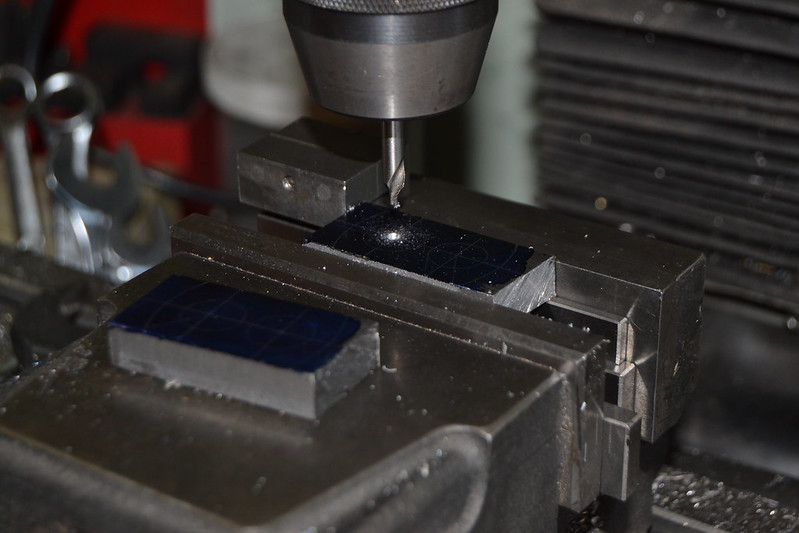
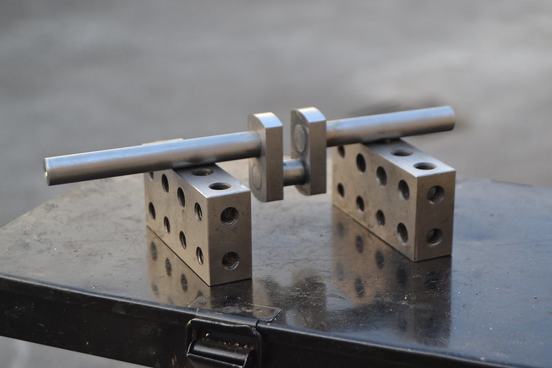
If you haven't already made a vice stop it's worth doing as it makes milling and drilling multiple components at the same setting easy.


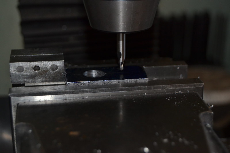
Although both shafts are 12 mm dia I've driiled and reamed the offset at 10mm, it's not really essential but I find a step in the pin diameters helps when assembling the parts and ensures the correct web spacing.


Next job trim off a bit of the waste to reduce the amount of interrupted cutting in the lathe


To radius the ends I made a close fitting mandrel.


That seemed to have the desired effect so the other end was done the same way


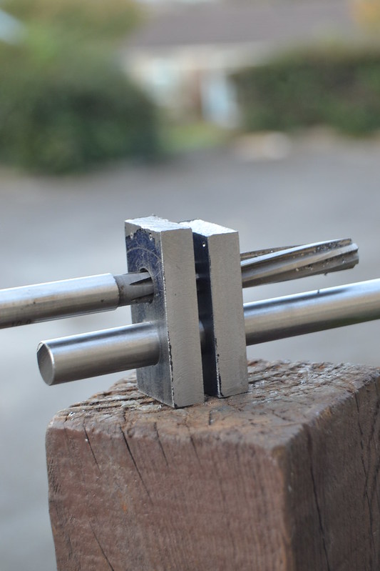
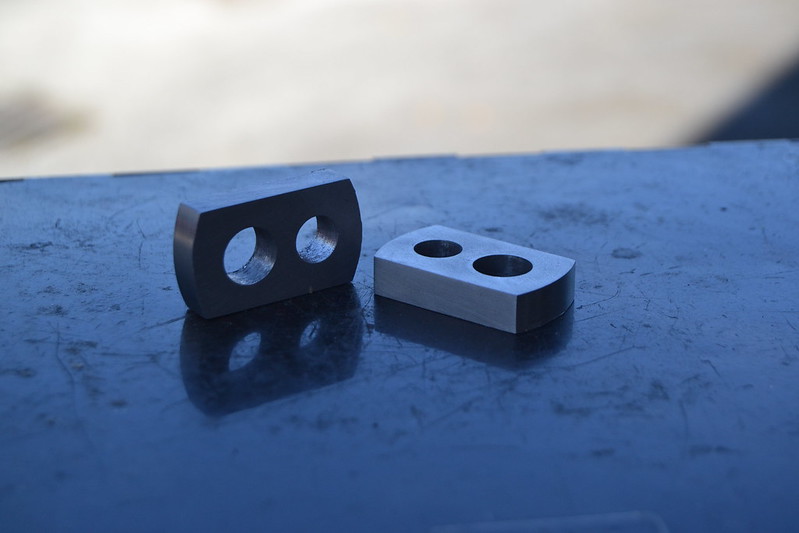
That takes me to this point (the holes are still full of oil and swarf but they are reamed)


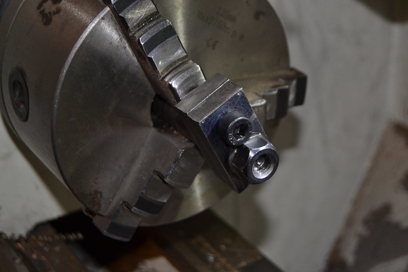
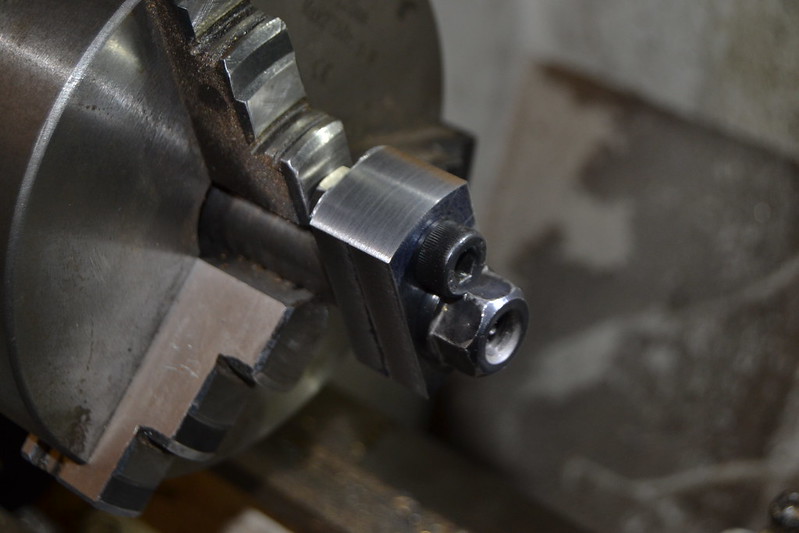
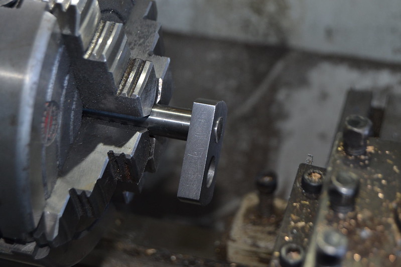
My 3 jaw chuck has a bit of run out and wont give the necessary accuracy to turn the crank pin so it's on with the 4 jaw and centre it properly to turn the 10mm dia stepped ends from the 12 mm silver steel rod.


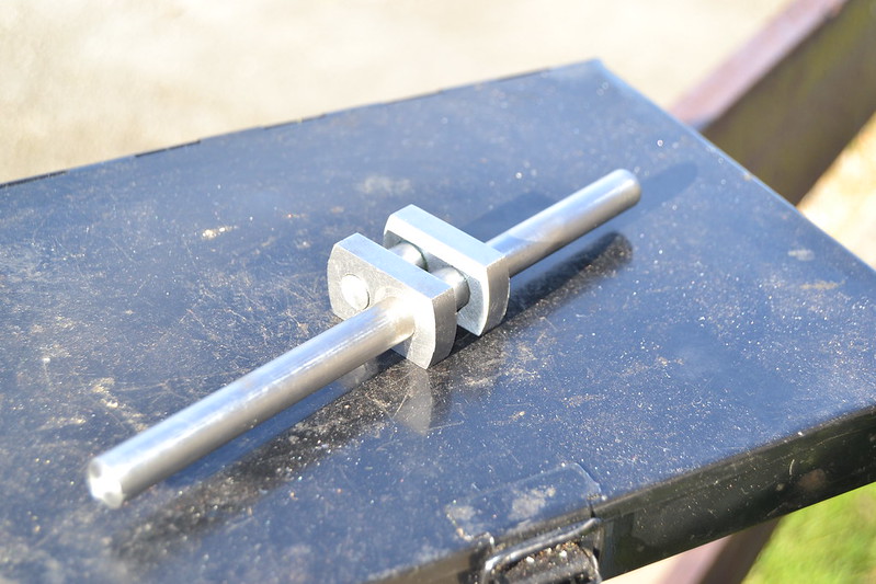
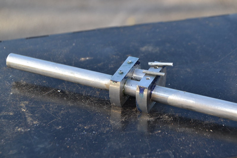
Satisfied that the parts fit together nicely they were glued together firmly secured using Loctite 638 high strength retaining compound.


Whilst there are decent sized mating surfaces for the Loctite to bond to it makes sense to add pins for additional strength, I've opted for 2.5mm steel (with hindsight I'd wish I'd done 3mm)  I'm never sure whether these pins are meant to pass right through the shaft and back into the web but in this case they go about 9mm into a 12mm shaft.


The pins will be secured with Loctite 638 then filed flush.


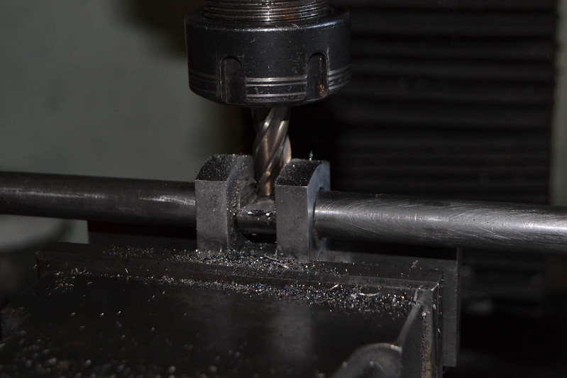
A simple job of milling out the waste centre shaft should pretty much complete the assembly.


A little bit of cleaning up gives me this finished part.


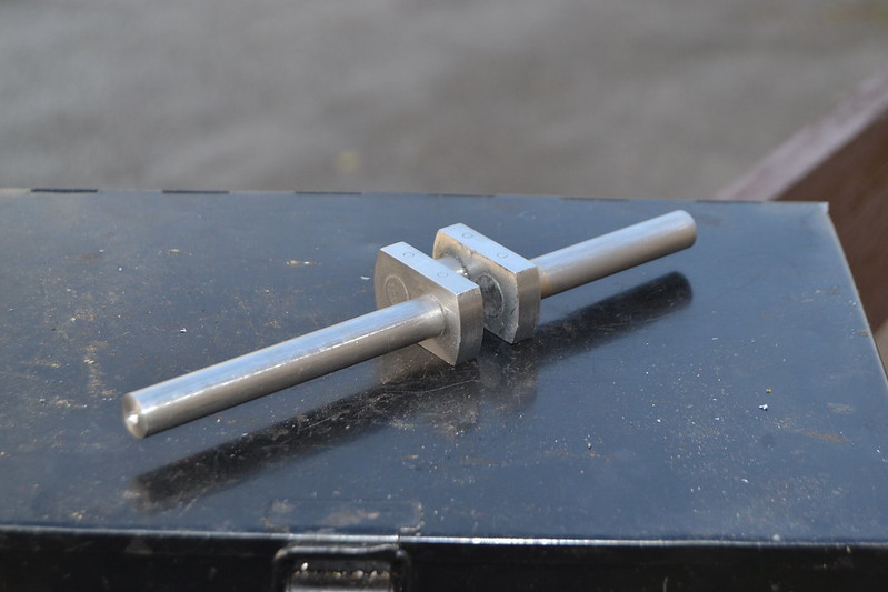
Nothing particularly exciting, but I'm happy with the result it sits nicely in the bearings and doesn't have any run out  :)

With the piston / crosshead assembly already in place it makes sense to next make the con rod, I tend to struggle with making them but I'm eager to get to the point where I can see how the piston and crankshaft operate once coupled together.

Peter


Online Kim

  • Global Moderator
  • Full Member
  • *****
  • Posts: 7916
  • Portland, Oregon, USA
Re: Little and large - building 2 vertical steam engines.
« Reply #192 on: October 21, 2018, 06:20:00 AM »
Very nice looking crankshaft, Peter!  Looks like it should do the job quite well  :ThumbsUp:
Kim

Offline Gas_mantle

  • Full Member
  • ****
  • Posts: 1365
  • North Yorks - UK.
    • My Youtube channel
Re: Little and large - building 2 vertical steam engines.
« Reply #193 on: October 21, 2018, 09:30:29 AM »
Thanks, it has been left to cure overnight and seems to have bonded well so hopefully it will have the necessary strength.  :)

Offline Gas_mantle

  • Full Member
  • ****
  • Posts: 1365
  • North Yorks - UK.
    • My Youtube channel
Re: Little and large - building 2 vertical steam engines.
« Reply #194 on: October 22, 2018, 05:01:35 PM »
A short update today but a bit closer to the goal of a finished engine

I'd like to get the con rod machined and in place this week but as this engine is a hybrid of part castings and part barstock some of the dimensions differ very slightly from the original Stuart plans. I'm making the parts based on what fits rather than rigidly sticking to drawings so before making the con rod I'd like to be able to see where the crosshead lies then machine the rod accordingly. So with this in mind it's time to mill out the trunk guide slots.

It's a bit of an irregular shape but using 4 clamps and a bit of packing I settled on this set up, I wanted a secure hold but didn't want to risk distorting the central bore and this seemed to fit the bill.


I guess there a numerous ways to tackle this but I find it easier to remove most of the waste material by drilling and keep the milling for the final stages.


A 10mm mill opens out the slot.


John Mills in an earlier post measured the width of the slots on his engine at 3/4" (19mm) so I expected to have to use a boring head to open out the end radii but after going through with a 16mm endmill I decided to stop there. They look about the right size now but I can always open them out later if need be.


Although a bit undersize I'm happy with the result, as long as I have access to the piston rod gland nut and crosshead pin I see no reason to alter things.


A bit of emery to remove burrs from the bore and the crosshead slides nicely  :)


That paves the way to make the con rod this week and see how the whole assembly turns over.

Peter


SimplePortal 2.3.5 © 2008-2012, SimplePortal