Hi Craig - nice to see a 'new face' thanks for looking in and glad it's provided a tang of nostalgia for you. I flew control line throughout my life from the age of thirteen. Though I have not flown since 2006 I still have two stunters hanging in the garage - a Nobler and a T'Bird.
Had a couple of Fox35's which were great motors for stunt - I think it has the reputation of being the longest model engine in production. It was a light and easy to run motor if a bit noisy. My preference however was for the OS Max 35
S which like the Fox 35 would run 4 stroke/two stroke if set right, right out of the box. I still have three from around twelve I was using at one time. Had a Fox 36 which was totally different kettle of fish - dreadful motor which I struggled with for some time before switching to the OS's.
Re the fuel guzzling - that was just it's second run from being built so was set very rich. None of the engines built so far have had much running - usually just once a year at a model event. Hope you enjoy the rest of the thread.
I now have all the ali parts save the con-rods done and have surprised myself how quickly the parts have been made. This is the work done so far so as you can see there is not much left to do

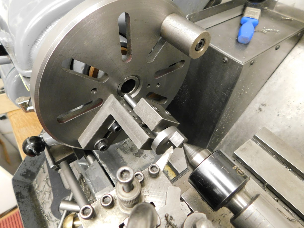
The crank shafts were done in my usual way of using a combination of EN24t and high tensile cap head material. This saves on En24t and has proved to more than stand up to the forces involved. The fixture is for turning the crank pins.....

.... using the faceplate.
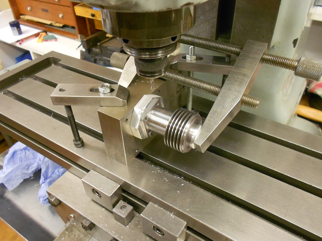
Finished except for the taper for the prop driver. Had to get one of those small revolving centres from Arc Euro to do that. Brilliant - should have bought one years ago


The cylinders do not have a liner and as such are turned from leaded EN1a. The machining was relatively straightforward but the two bulges that are over the transfer passages required a different approach which you may find of interest .......
First up was to finish turn the bore and rough turn the basic ODs

Make a new expanding mandrel to suit the bore and machine the fins and lower flange dimensions

Then modify an old one to hold it on the mill .....


The teeth of an end mill cutter were modified on the offhand grinder.....

...... to plunge mill the transfer passages in to an exact depth

Set back on the longer mandrel the exhaust side of the case had the relief milled in

Finished example and the transfer side to do - the bulges required can be seen in the drawing. I would assume the original was machined on a copy lathe but with no access to such another means was sought.

A fixture was made to hold the cylinder via the hold down bolt holes. The two larger holes sit on the centres of the transfer bulge radii

A block was set square to the mill table with a pin set in for the fixture to rotate about

then by rotating small movements and clamping the radius was slowly formed. Once done the cylinder was moved to the second hole and the machining repeated
Back on the small mandrel to cut the scallops out - the bulges can be clearly seen here

And finally - finished ready to lap

That's it - have to go - Sues chomping at the bit - lunch with the in laws - you know the score
Hope that's of interest - I was well pleased with the way those transfer passages turned out - hope that's of use to some one
Regards - Tug
No time to preview this so any mistakes will be rectified later


