Author Topic: CHUKY - Build One Yourself  (Read 17530 times)

Offline Jasonb

  • Full Member
  • *****
  • Posts: 9493
  • Surrey, UK
Re: CHUKY - Build One Yourself
« Reply #15 on: June 17, 2017, 08:53:47 PM »
Next put your parting tool in the toolpost, set the front edge to touch the work and zero the cross slide dial. Then with the topslide touch the edge of the tool against the end of the cylinder, retract and move half the width of the cutter towards the headstocjk and then zero the topslide handwheel. This will make it easy to set the spacing of the fins as they are all dimentioned to their ctr from the top of the cylinder OD.

First make a central cut on each 5.5mm deep.


Then increase the width of the slots to 4mm by taking a equal cut off each side of the first grooves.


Then swing the topslide around to 5degrees and cut the taper down one side of each fin. Swing to 5deg the other side of zero and make a similar set of cuts down the opposite sides.


Grind up a 4mm square HSS tool bit to a half round profile and then round out the bottoms of the grooves, a slow speed will be needed to avoid chatter.


Then with a file the external corners can all be rounded over whith the lathe running.


Remove the tailstock and trim the spigot back to its final 5.0mm length.


With the largest part of the lower cylinder uppermost mill it back flush with the edge of the fins or just a fraction proud. Use a nice sharp cutter as we want a good finish here to save excessive lapping later on.


Centre up the port face and drill two 4.0mm holes 10mm each side of ctr into the bore, then another four holes will remove most of the material from the inlet passage. Finish up by cleaning out the slot with a 4.0mm milling cutter.


The cylinder can then be held bottom up on the rotary table and the two sides of the port machined as was done to the base.


Then again like the base round the rest to 42mm dia


Then add the four holes but this time thay are tapped M3.


Finally for now the five M2.5 hole scan be drilled and tapped in the top but make sure you drill them in the right place unlike me :-[ the one above the port face should be left out.


J


Offline Jasonb

  • Full Member
  • *****
  • Posts: 9493
  • Surrey, UK
Re: CHUKY - Build One Yourself
« Reply #16 on: June 18, 2017, 05:22:17 PM »
Although I'm not a fan of them myself I was asked on ME forum about a Bill of Materials so here is one you can download.

Bill of materials

Offline Dave Otto

  • Full Member
  • *****
  • Posts: 4712
  • Boise, Idaho USA
    • Photo Bucket
Re: CHUKY - Build One Yourself
« Reply #17 on: June 20, 2017, 12:51:21 AM »
Continues to be an interesting build Jason.
Thanks for the update.


Dave

Offline Jasonb

  • Full Member
  • *****
  • Posts: 9493
  • Surrey, UK
Re: CHUKY - Build One Yourself
« Reply #18 on: June 21, 2017, 05:47:56 PM »
Bearing Support

Drawing #4

I mentioned at the start that there were two pieces that are silver soldered fabrications, this is one of them and it is the one that if you are not able to silver soilder too well could probably be done by machining the vertical part into a "+" section and then tap this top and bottom for a couple of M2 CSK fixings each end. Though it would also be a good thing to get the hang of silver soldering on as there is not much material in it and if the worse came to the worse it could be melted apart, cleaned up and another go at soldering attempted.

I have shown the finished sizes on the drawing but strongly suggest that the top piece is made of something thicker than 3mm material and also left ovesize in the other two directions. It is unlikely that you could solder it all in exactly the right position but by leaving the top oversize it can me treated like a casting and machined exactly right once soldered.

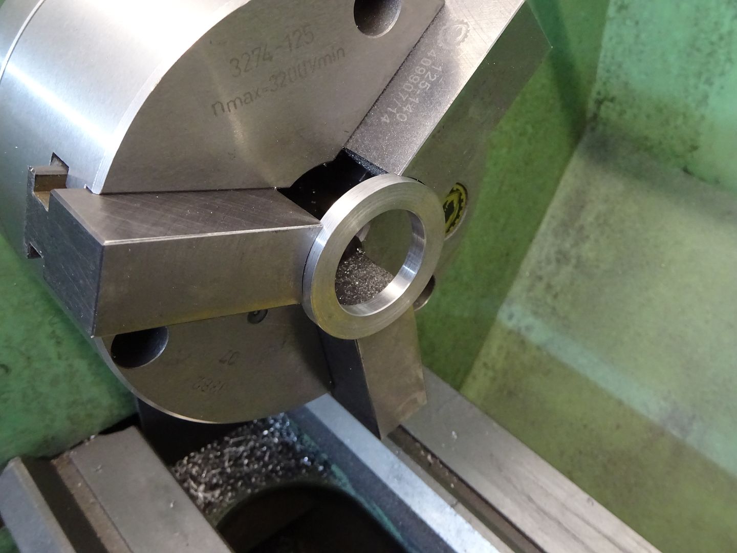
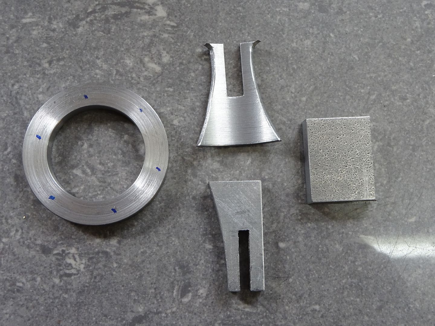
So make a start on the lower ring. Chuck a piece of 45 or 50mm dia bar, turn down a short length to 42mm dia, face the end and then drill and bore out to a nice snug fit on the 28mm spigot left on teh top of the cylinder. Saw or part this off and then face back to the finished 5mm thickness


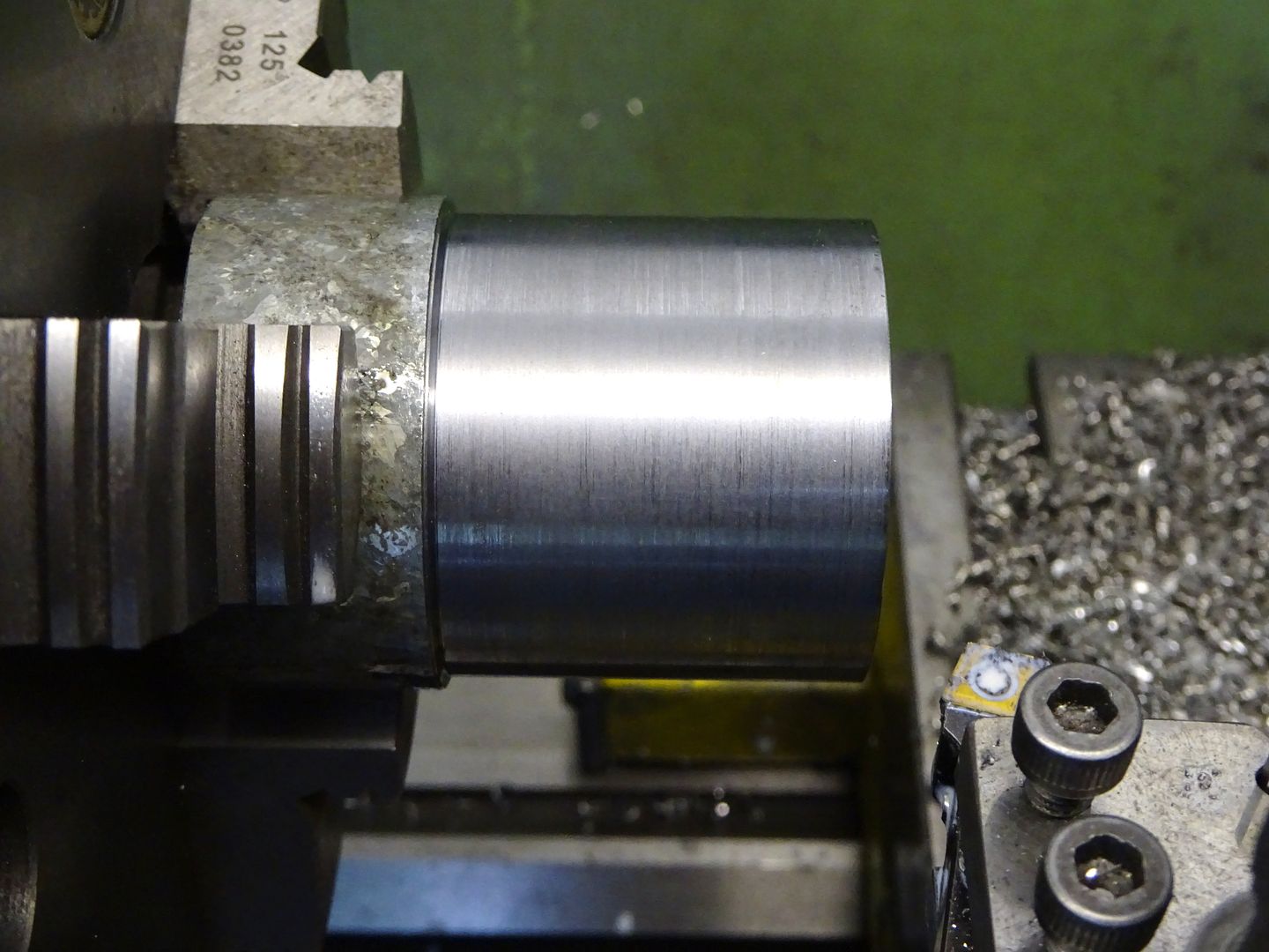
For the curved part of the upright I used a short length of scaffold pole skimmed inside and out to clean it up and then faced both ends to bring it to 32mm long. It could be cut from solid or even bent up from some 3mm flat, the exact curve is not really that critical.


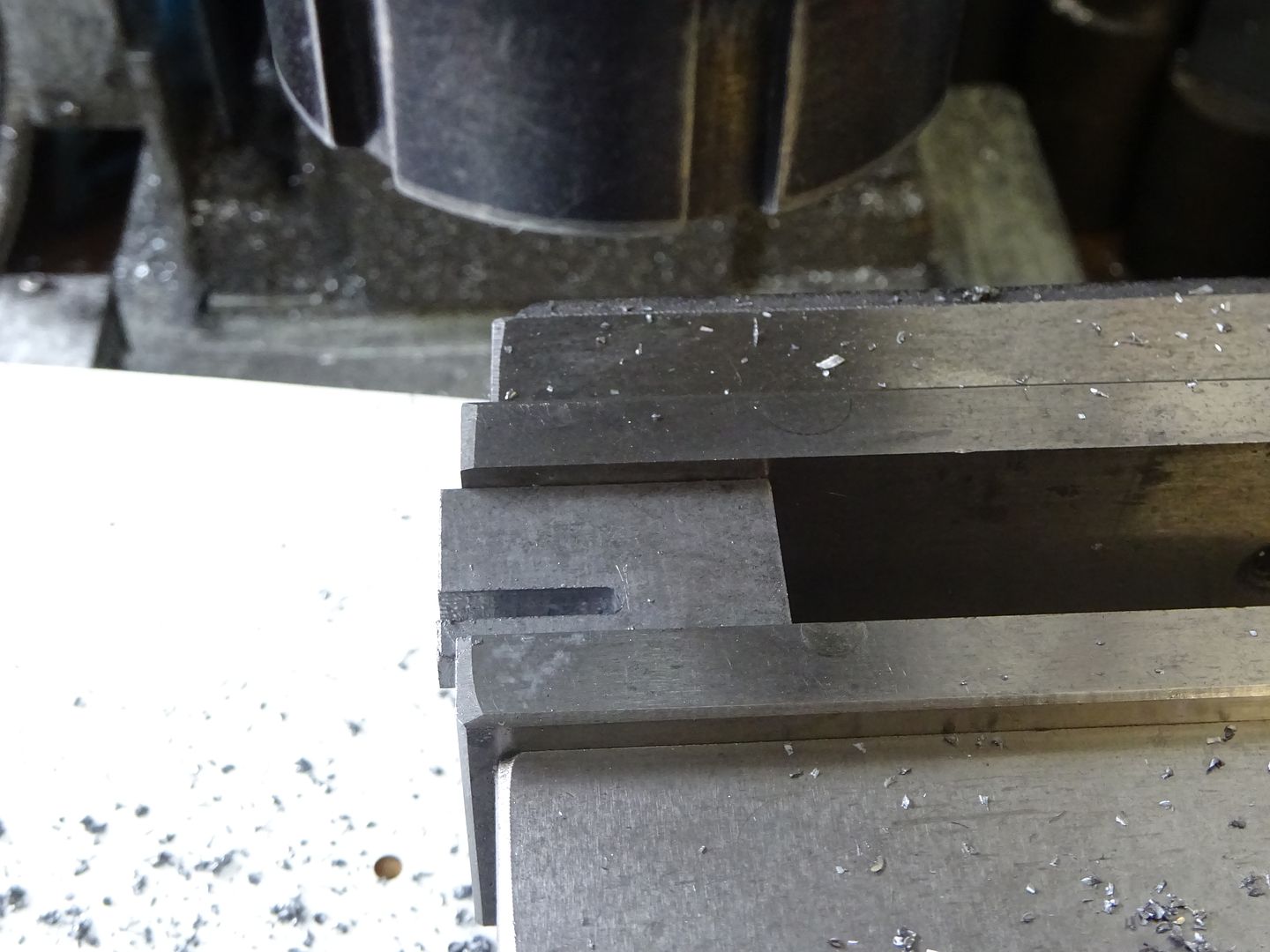
The cross shape is made with a halving joint so mill a 5mm slot half way up.


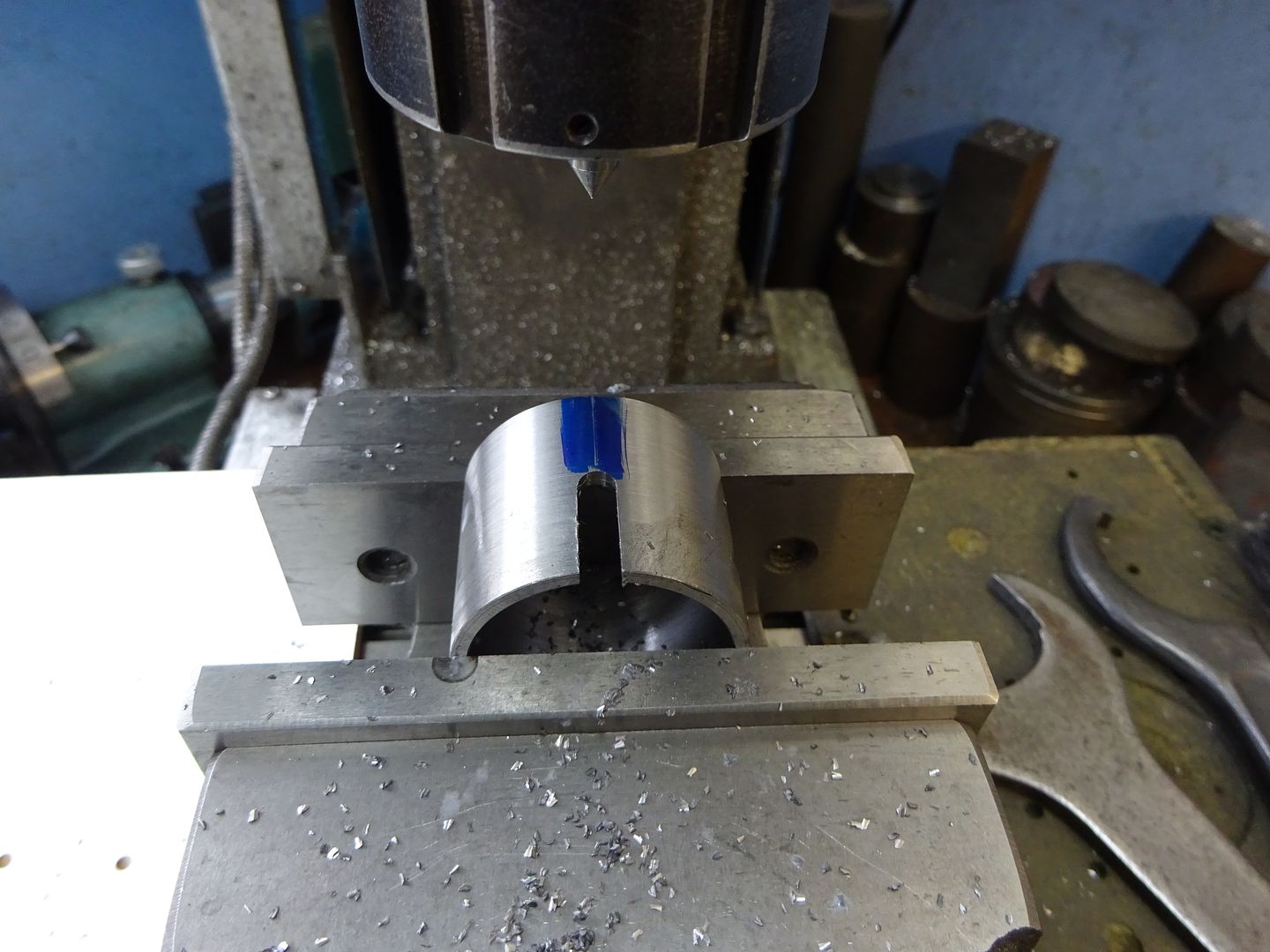
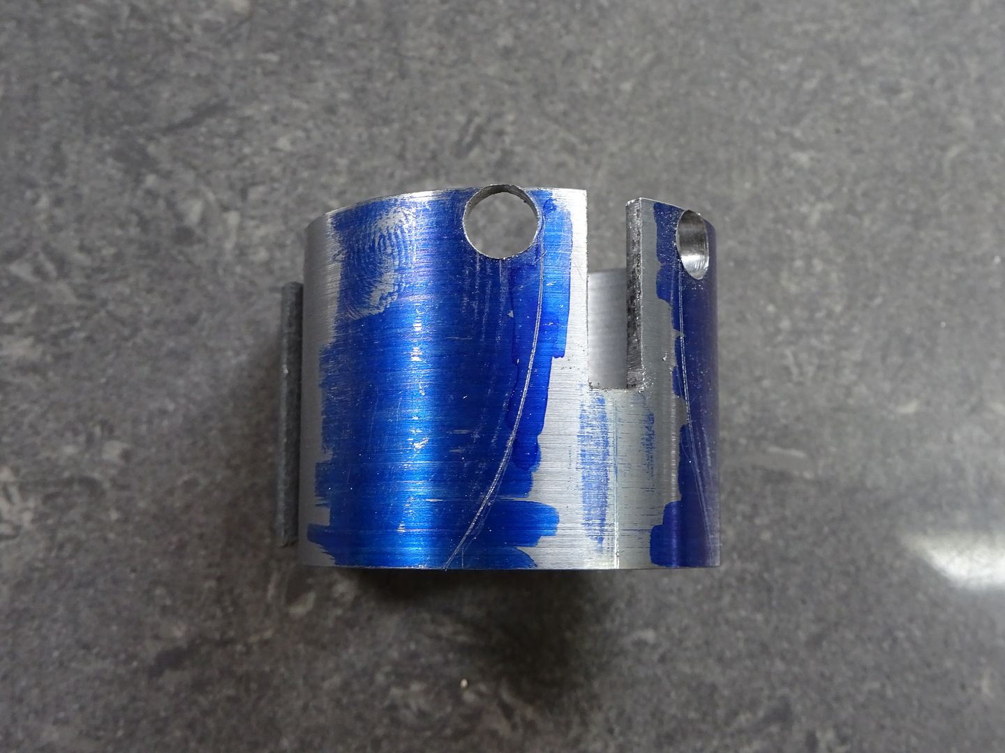
Then mark out a pleasing shape. I drilled 5mm at the top to leave a nice fillet shape and then drew the two larger curves by scribing around a roll of masking tape. Saw and file to your chosen design.


The other part of the cross is cut from a bit of 5mm flat plate and has the other half of the having joint milled in it a 3mm wide. Finally cut and file to shape. I would suggest the face that the valve rod guide screws to is also left overside at this stage.


Another bit of the 5mm stock forms the top plate, these are the 4 parts prior to soldering.


Give them a good coat of HT5 or Tenacity5 flux and place on the hearth, a couple of bits of scrap metal can be used to help steady things. Put a bend in your solder rod before starting to heat as it makes it easier to apply the first bit of solder under the top plate then chase the heat down with the flame watching the solder flow as you go adding more as needed.


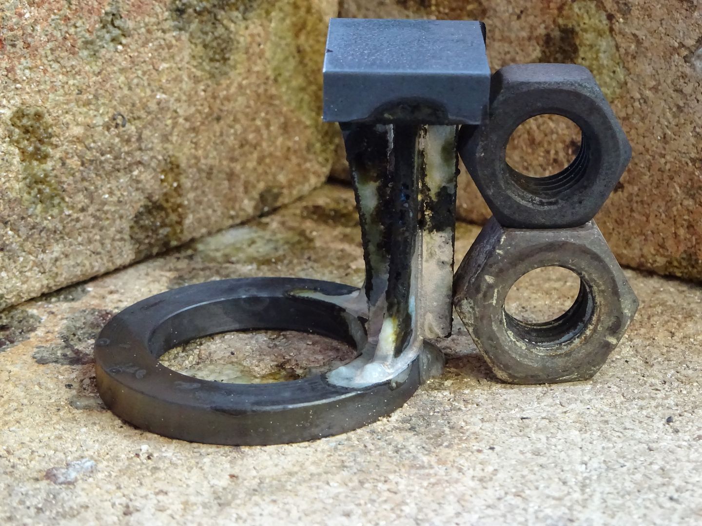
Once cooled give the part a soak in your chosen pickle I tend to use brick cleaner now as it shifts all the black scale from soldering steel as well as the HT5 flux.

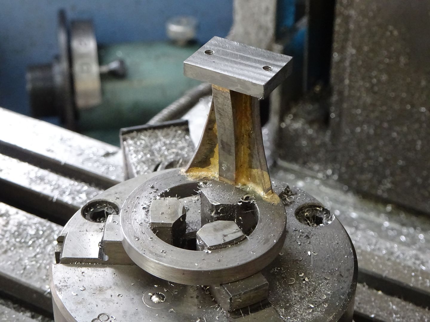
The part can now be held on the mill either using a chuck or clamped to the table. If holding in a small chuck as I have shown add a clamp or two to hold it down because the leverage from milling the top can pull it about a bit and result in a chip to a nice new milling cutter :-[ With it held in place locate the centre of the hole and from there the 4 sides of the top can be machined to the drawing dimentions and the two M2.5 holes drilled & tapped. Then mill the top down until the 40mm height is reached.


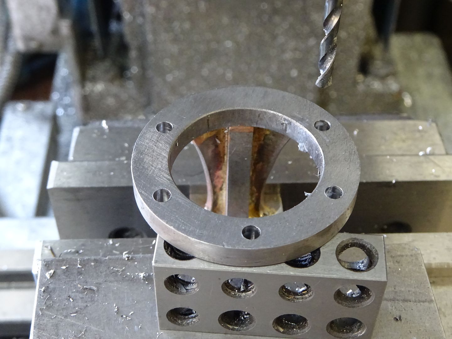
Now with the bracket upside down in the mill vice locate centre and drill the five M3 clearance holes on as 35mm PCD, support the overhanging edge so it does not move under pressure from the drill.


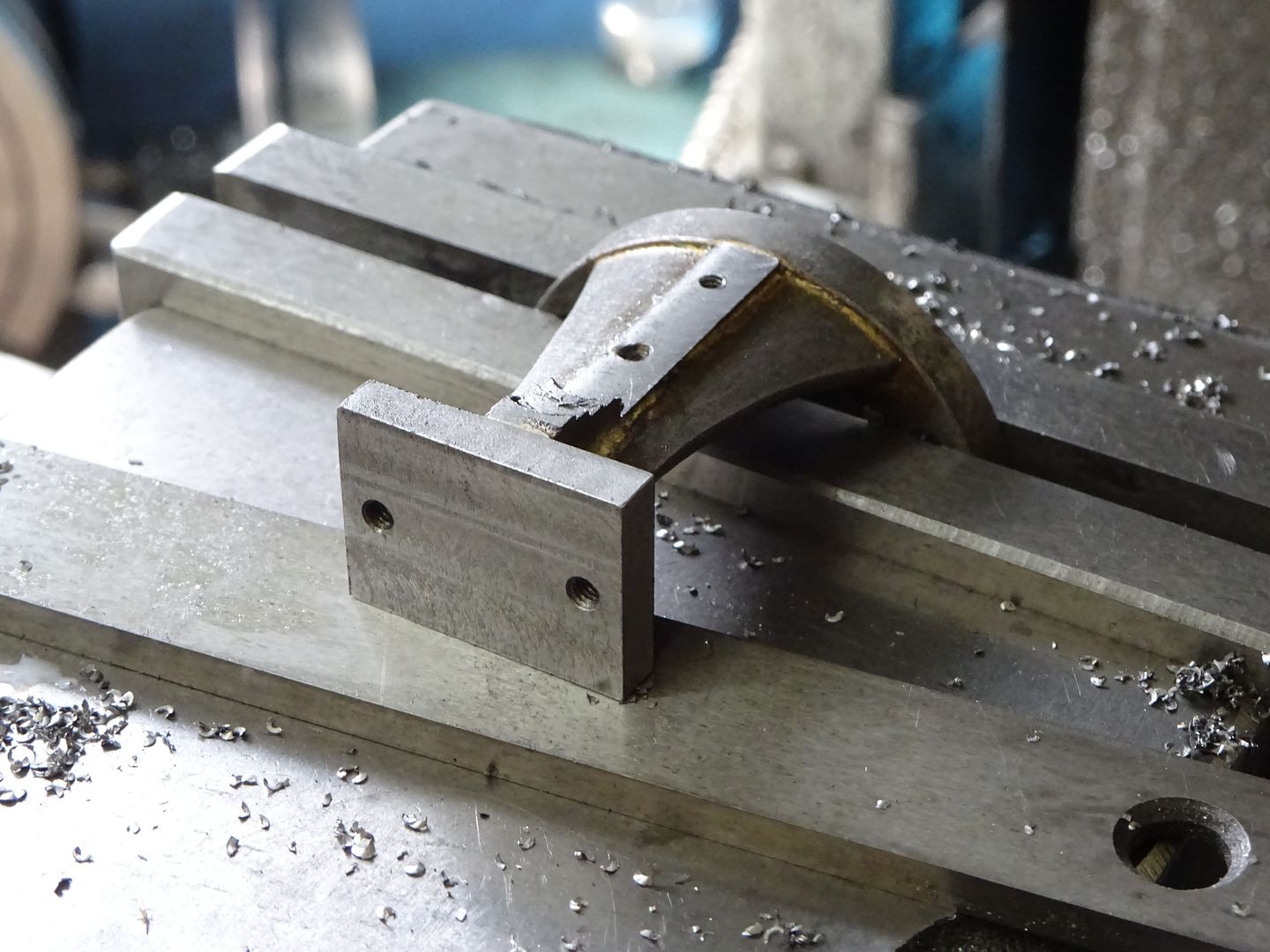
Holding by the round ring and with the long side of the top on the flat of the vice the surface for the valve rod guide can be milled back until the cutter just skims the edge of the ring which will put the surface 21mm from ctr. Don't mill right upto the top plate but feather out the cuts and afterwards file to a pleasing radius. The two M2 holes can also be drilled and tapped at this time to complete another part.


J

Offline crueby

  • Full Member
  • *****
  • Posts: 18708
  • Rochester NY
Re: CHUKY - Build One Yourself
« Reply #19 on: June 21, 2017, 07:31:29 PM »
Nicely done! Watching along....     :popcorn:

Offline Jasonb

  • Full Member
  • *****
  • Posts: 9493
  • Surrey, UK
Re: CHUKY - Build One Yourself
« Reply #20 on: June 25, 2017, 06:41:02 PM »
Piston and Associated Parts

Drawing #5

Before starting on the piston it is best to hone the cylinder, this can be done quite easily with one of the cheap brake cylinder hones. I run these in the bench drill at about 750rpm and just move the cylinder gently up and down making sure not to let the stones stick out too far and risk a bell mouth end, a little paraffin will help stop the stones clogging.

The piston will come out of a length of 25mm cast iron bar, face it off then turn the outside until it just enters the cylinder bore. Check against both ends of the bore, if one is smaller then use the hone some more to remove any taper. Once you have a push fit into the cylinder stop working on the outside and bore the inside followed by drilling and tapping for the M3 thread.


Saw or part off the piston and then face off to 20.5mm finished length being careful not to distort or crush the now hollow piston. Face off and tap a bit of say 12mm bar to take an M3 screw and this can be used as a mandrel to hold the piston while it is lapped into the bore.  This is easily done at a slow speed with a small amount of 1000g silicon carbide powder and a liberal amount of oil. Just work the cylinder onto the piston from the top until it is a close but friction free fit. Clean off all traces of SiC powder.


The lug for the gudgeon pin can first have the end reduced down to 3mm and then be threaded M3


Then mill it to a square section if you have not started with square bar. This can then be cut off the main bar and milled to length and a 3mm slot cut into it.


Followed by the drilled and reamed cross hole after which the end can be rounded off by filing or machining.


The gudgeon pin is a simple turning job. Onec done blue the end, put it in teh hole and mark off the position of the split pin holl. Then drill for a 0.8mm (3/32") split pin.

This pic shows the finished parts along with the conrod which is still to be descibed.


J

Offline crueby

  • Full Member
  • *****
  • Posts: 18708
  • Rochester NY
Re: CHUKY - Build One Yourself
« Reply #21 on: June 25, 2017, 07:12:14 PM »
For the paraffin to prevent clogging the hone, is that the solid type paraffin wax, or kerosene liquid?

Following along, nice work!

 :popcorn:

Offline Jasonb

  • Full Member
  • *****
  • Posts: 9493
  • Surrey, UK
Re: CHUKY - Build One Yourself
« Reply #22 on: June 25, 2017, 07:39:08 PM »
Just the liquid Kerosene, I put a few drops on at the top and let it run down and out the bottom taking the dirt with it.

Offline Gas_mantle

  • Full Member
  • ****
  • Posts: 1365
  • North Yorks - UK.
    • My Youtube channel
Re: CHUKY - Build One Yourself
« Reply #23 on: June 25, 2017, 10:51:12 PM »
Looks great Jason  :)

What sort of soldering equipment are you using ?  I like idea of fabricating parts rather than using castings but wonder if my simple Mapp gas set up will cope

Offline Jasonb

  • Full Member
  • *****
  • Posts: 9493
  • Surrey, UK
Re: CHUKY - Build One Yourself
« Reply #24 on: June 26, 2017, 07:41:25 AM »
I have an old Bullfinch torch that runs off a 3.9kg propane bottle with about a 22mm burner. A mapp torch would probably do this bracket OK as the bits are reasonably small so you don't need as many Kw as a big burner puts out. Mapp would certainly be OK for the other part that must be soldered and that is the shutter.

As a half way measure "Comsol" could be used which has its melting point between soft and silver solder.

Offline Gas_mantle

  • Full Member
  • ****
  • Posts: 1365
  • North Yorks - UK.
    • My Youtube channel
Re: CHUKY - Build One Yourself
« Reply #25 on: June 26, 2017, 08:23:48 AM »
Thanks, I quite fancy having a go at making one of these engines once my new lathe arrives.

I've silver soldered a few parts in mild steel using a small Mapp torch to fabricate something but they were quite small.

Offline Alyn Foundry

  • Full Member
  • ****
  • Posts: 1654
  • North Wales, Great Britain.
Re: CHUKY - Build One Yourself
« Reply #26 on: June 26, 2017, 11:49:12 AM »
Hi Jason.

Proceeding nicely.

Insulation.... A key word. For Silver soldering we used Ceramic fibre wool surrounding the object. It matters not how big the heat source is, if you let that heat escape the object won't heat up.

The wool is so reflective that objects quickly get up to the required temperature, I also recommend Tenacity 5. It works really well on the Ferrous range of materials, still working even with prolonged heat exposure.

All my " homespun " furnaces  were lined with Ceramic fibre, we cast most prototypes at home before moving on to the foundry.

Another well known tip, particularly useful if you're a bit shaky, is to cut pieces of solder, fluxed, and place them strategically around the object. My technique was to play the heat around the outer area and get it hot before going into the joint proper. This method ensured that the whole object expanded and, in theory contract without twisting.

Kind regards, Graham.

Offline Jasonb

  • Full Member
  • *****
  • Posts: 9493
  • Surrey, UK
Re: CHUKY - Build One Yourself
« Reply #27 on: July 03, 2017, 07:10:28 PM »
Crankshaft Parts

Drawing #6

I made a start with the crank web and to make it easier to hold actually machined it on one end of a short length of 40mm dia steel bar and the cam on the other end.

Start by facing the end of your stock, then using a tool with a small radius on the corner turn the 3mm long spigot and also the 38mm OD. Followed by drilling and reaming the central 5.0mm hole.


Transfer to the mill, locate centre and then use the handwheel dial or DRO to move 16mm and then drill and tap M3.


Saw or part off and then holding by the spigot clean up the other side but leave the web about 0.5mm over thickness at this stage. Mark out the two straight edges, saw off the waste and then mill back to the lines.


A bit of simple file work will round off the edges.


The crank shaft can be made from precision ground mild steel (PGMS) or silver steel, stainless would also be OK if it is a good fit in your bearings. Face it off either end but leave it 1.0mm longer and then turn the spigot also 1.0mm over length. The crank web can be used as a gauge to get the spigot a firm push fit into the hole. Once done clean up both parts and loctite them together.


Once the Loctite has had a good time to set the crank can go back into the lathe to have the web faced down to the final 3mm thickness. Doing it this way will ensure the face of teh web is at right angles to teh shaft even if it went on a bit crooked when loctited.


The crank pin is fairly straight forward turning, put a small undercut at the base of the thread to ensure it screws right into the web and the shoulder makes contact. Saw or part off then clean up to leave the lip 1.0mm thick and add a small chamfer.

J

Offline crueby

  • Full Member
  • *****
  • Posts: 18708
  • Rochester NY
Re: CHUKY - Build One Yourself
« Reply #28 on: July 03, 2017, 07:26:54 PM »
Another great installment, nice sequence


 :popcorn:

Offline Jasonb

  • Full Member
  • *****
  • Posts: 9493
  • Surrey, UK
Re: CHUKY - Build One Yourself
« Reply #29 on: July 13, 2017, 07:20:15 PM »
Thanks Chris


Cam Disc

Drawing #7

I machined this on the other end of the bit of 40mm dia steel that the crank came out of.

Start by facing the end and then turn the 12mm dia x 6mm long spigot followed by drilling and reaming 6.0mm


The cam can be formed in a number of ways: milling, turning in the 4-jaw or even filing to the template included on the drawing. I opted to mill it using the rotary table as follows

- centre the rotary table under the spindle and zero the dials or DRO, lock y axis
- hold work in chuck , put a 6mm rod in the collet chuck and bring down into the hole
- move table 11mm in the x plane allowing the chuck to slide along the rotary table
- Bolt chuck to R/T
- Fit a cutter into the collet chuck and work your way in from the edge rotating the work on the table until the x axis is 25mm plus half your cutter dia.


Saw off from the rest of the bar and then hold by the spigot in the 3-jaw, face back to 3.5mm thick and then take a further 0.5mm cut but stop to leave the 8mm raised area in the middle which will make sure the cam only contacts the bearing inner race.


You could mill the two 10mm radius corners that blend the arc into the main diameter but I just opted to file it to shape.

Final job is to drill and tap for a M3 grub screw.


J


SimplePortal 2.3.5 © 2008-2012, SimplePortal