
I built this model quite a few years back and thought it may be of interest.
It's a very near scale model of a full size engine in the Northern Mill Engine Society collection in the UK and was built from castings and drawings produced by 'Helix Engineering', a father and son team who had access to the original engine. The quality of the castings was truly superb and the drawings even better. Infact I would go so far as to say the drawings were just as good as drawings used on a daily basis at work.
The main casting was a hefty lump and was held to a 'home made' angle plate (well works 'sponsored' - I had an extremely understanding and generous boss for such things) the only tricky bit being to ensure that the cylinder mounting areas were equally true to the centreline through the crankshaft.

The trunk guides were bored first and then held on an expanding mandrel to bring the base flange true to the bore. I find this method much easier than trying to position the bore true to a face


The con rods were machined from solid starting life as quite beefy square section blocks....
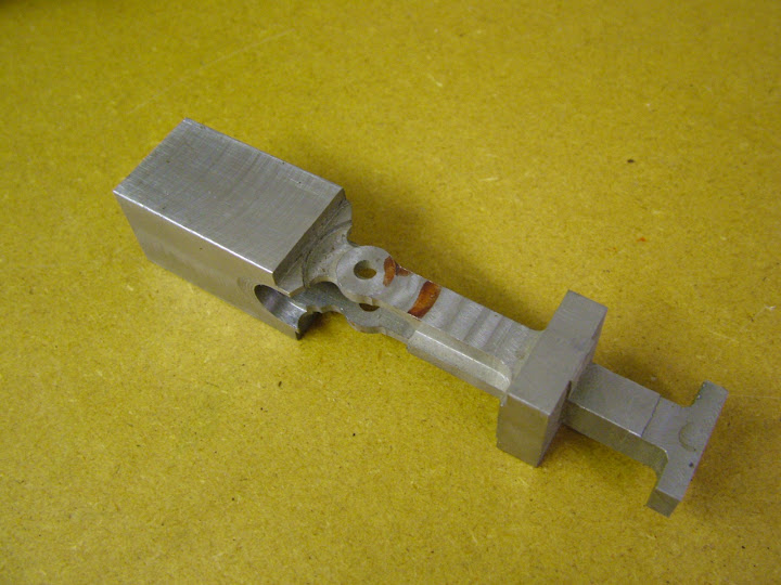
I keep this as a reminder

I can't remember what is wrong with it but it was a scrapper fairly early on in the proceedings. The thing is, once realised, I turned to a spare bit of material and brought it to the same stage before retiring for a cup of tea. Came back and carried on to the stage you see before realising I had picked up the scrapper instead of the new part


The valve rod guides are fabricated and silver soldered. They were made with a solid base with the central guide aligned in a hole the curved parts cut from a ring. Once soldered the base and lower part of the guide were machined away

The exhaust is an annular cavity around the liner. The lagging was made from .006" steel shim and heat treated in the (kitchen) oven - can't remember the temperature but several test pieces were done before getting a satisfactory colour.

Once assembled the only fettling required to enable running was to open the diameter of the trunk guide slightly to give clearance to the conrods. It was essential to get the centrelines right to keep the angular movement equal. It doesn't look like it but the clearance is not much more than ten thou.

The stop valve was fabricated and treated with an engraver as described for the Waller engine. The full size engine had no governor but was coupled direct to a calico printing press, speed being controlled by the valve - dependant on the variety of print required I guess.
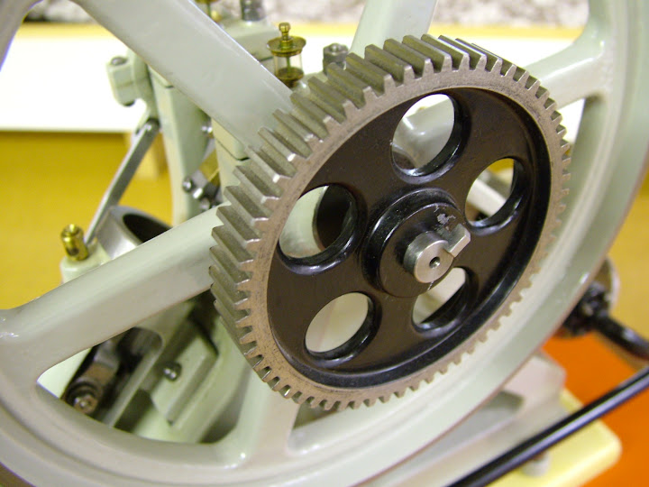
And finally the benefits of being at work now so sadly missed - but only at certain and very specific times you understand

- the gear wheel was the first 'homer' done on the new Mitsubishi wire eroder

I had no idea of the colour of the original but decided on using the polyurathane paint used for the milling machine. It would be years later before I saw this ...
http://www.nmes.org/albums/main/diagonal1.jpgIt's been nice to be able to post something so soon but it will be a while before there's something else underway but it'll come soon enough I guess.
Hope that's of interest to someone
Regards - Ramon


