Author Topic: Building a bigger Easton & Anderson Grasshopper  (Read 108954 times)

Offline zeeprogrammer

  • Full Member
  • *****
  • Posts: 6811
  • West Chester, PA, USA
Re: Building a bigger Easton & Anderson Grasshopper
« Reply #90 on: December 16, 2012, 09:31:31 PM »
Superb Jason. The quality of work is amazing.
Carl (aka Zee) Will sometimes respond to 'hey' but never 'hey you'.
"To work. To work."
Zee-Another Thread Trasher.

Offline Don1966

  • Full Member
  • *****
  • Posts: 6818
  • Columbia, MS
Re: Building a bigger Easton & Anderson Grasshopper
« Reply #91 on: December 16, 2012, 09:41:27 PM »
You my friend are a medal artist, beautiful work.

Don

Offline Jasonb

  • Full Member
  • *****
  • Posts: 9495
  • Surrey, UK
Re: Building a bigger Easton & Anderson Grasshopper
« Reply #92 on: December 26, 2012, 07:27:20 PM »
With the beam and end support frame done I decided to tackle the cylinder next as this will eventually allow me to support the other end of the beam. I started with the base flange, this was sawn into a octagon from some 5/8"x4" flat brass bar and held in the 4-jaw to trepan out the centre. I went almost half way from each side then took it out of the lathe and gave the middle a whack with a hammer and the central disc dropped out.


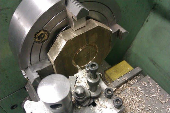
The bore was cleaned up and then used to hold the flange by while the outer edge was machined round.


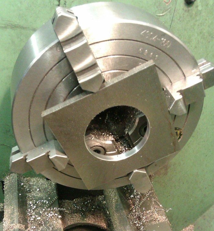
I then preceeded to do the same for the top flange but from 1/4" thick material, it was just as I finished trepanning out the middle that I remembered I should not have cut the corners off :wallbang: so substituted a piece of 1/4" steel as I did not have another piece of brass large enough.


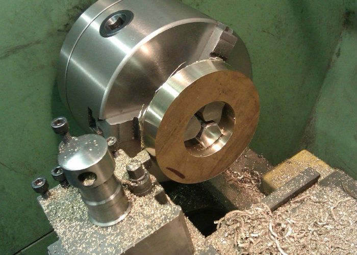
The main tube of the cylinder started life as a length of 2 1/2" hollow cast bronze


The outside was turned down to 2.375" and spigots formed on the ends for the flanges to fit onto. At this stage the bore was left undersize for finishing after fabrication, the overall length was also 1/16" bigger than needed so the flanges could be skimmed back true to the finished bore.


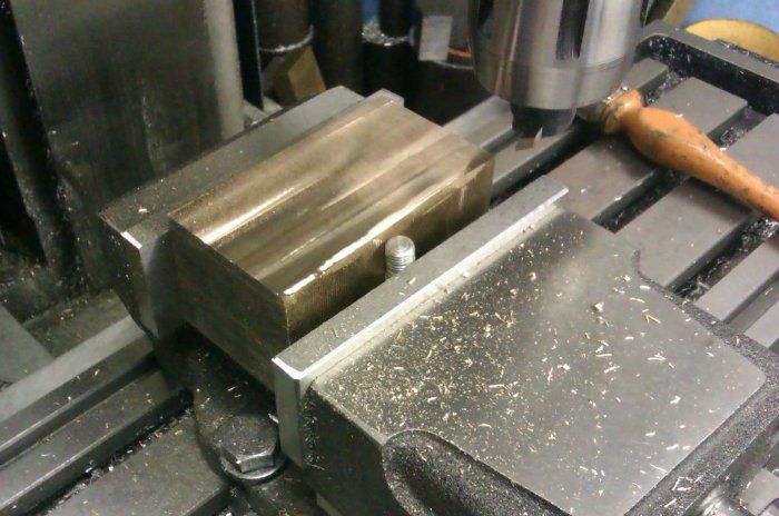
A lump of bronze was sawn to give me a finished block of 3.25 x 1.5 x 1.75 and this was flycut to get all faces square.


Finally a bit of 1/8" brass sheet was cut to make the flange for the valve chest cover to bolt to and here are the roughed out parts.


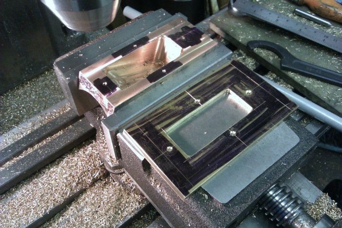
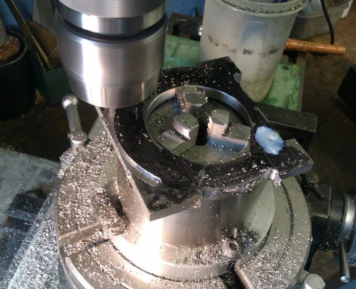
I used a boring head to cut the curved face of the valve chest


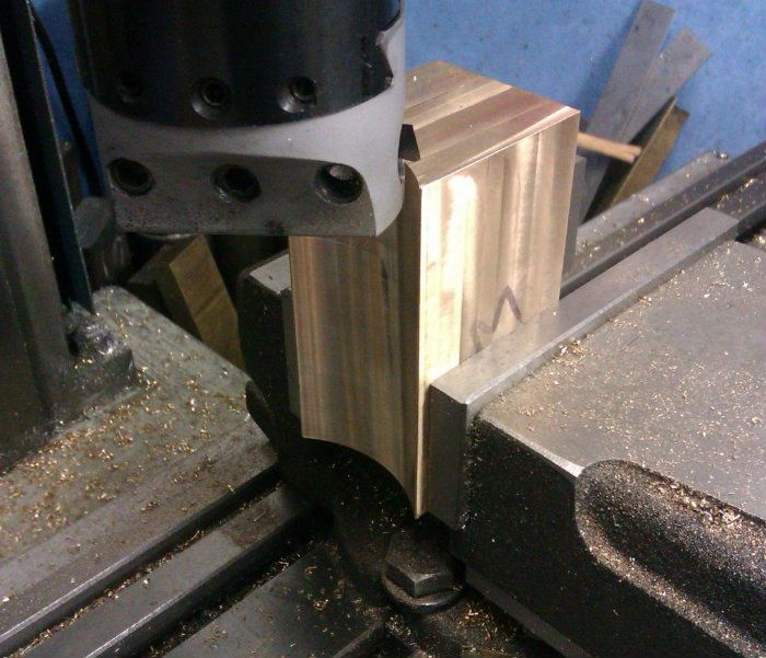
The chest was then cut off at 20degrees, the chamber roughly hollowed out and the angled face flycut. I also cut a matching hole in the bolting flange and added a few 10BA CSK screws to hold the two together when soldered.


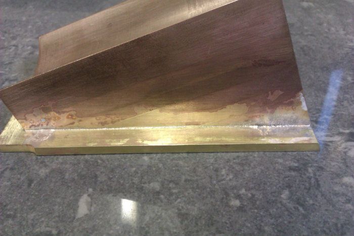
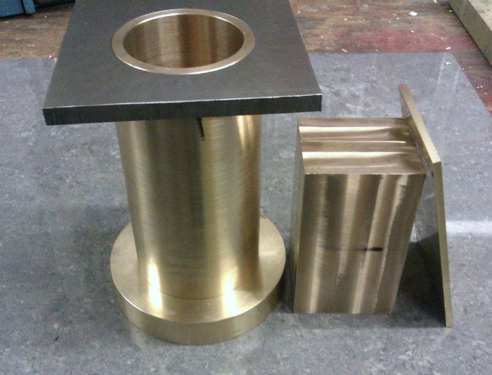
Starting to look a bit more like the original now


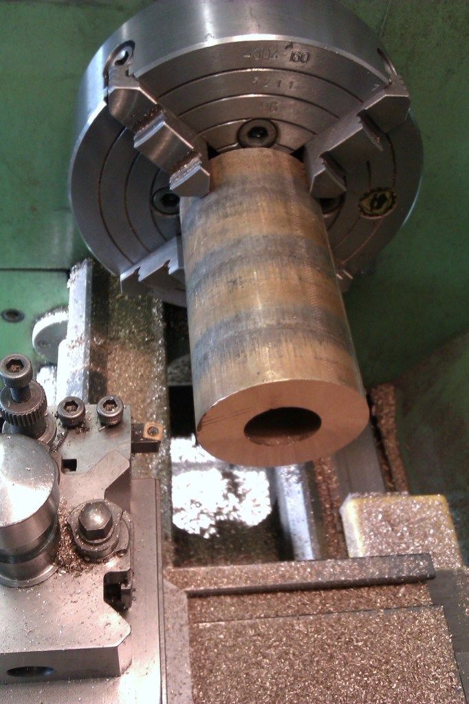
As the cylinder was comming together it became obvious that I would have difficulty holding it to take any heavy cuts off once assembled as I could not get it into my fixed steady so I decided to do a bit more work on it before soldering. Also the valve chest needed quite a bit of heating to get the solder to flow and by removing any unwanted metal the bulk would be reduced making for slightly easier heating. Here is the cylinder barrel getting opened out.


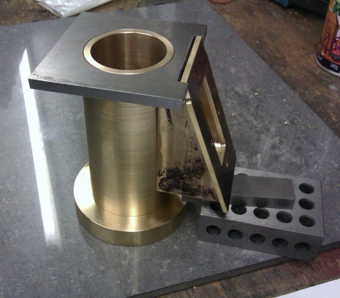
I also shaped the top flange, now you can see why I needed the corners, they will support the "A" frames which help retain the beam.


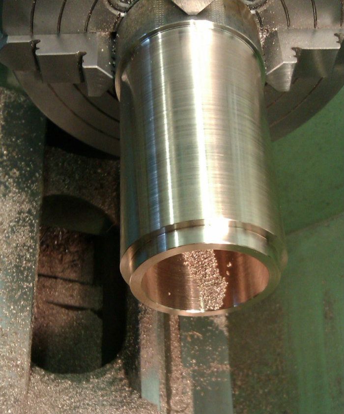
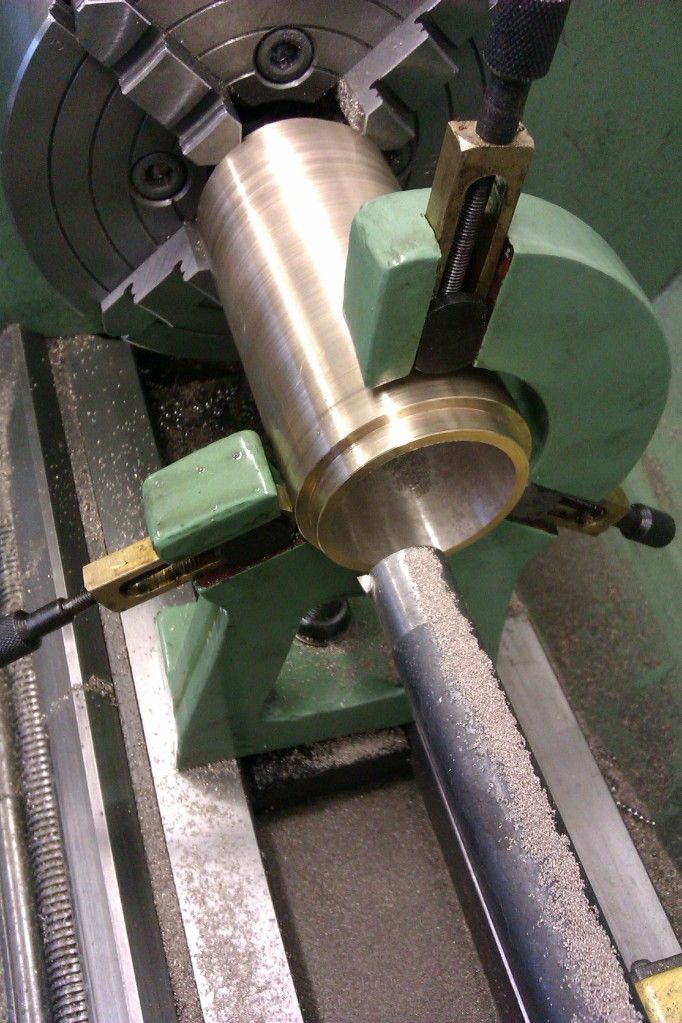
Once all the parts had been machined I silver soldered them together, It went OK but not what I would call perfect as it was hard to get enough heat into the big lumps of bronze. Once cleaned up I spent a long time clocking the cylinder true in the 4-jaw both for concentricity and alignment to the lathe axis, changed the QCTP to the 4-way that came with the lathe so I could mount a 7/8" boring bar and just skimmed the bore with several very light passes followed by similar light cuts to the top flange.


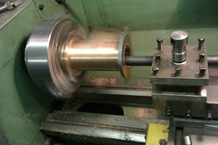
On a safety note, don't try this unless you know what you are doing there is a lot of unbalanced metal hanging a long way out the chuck. If in doubt then don't.

This post is getting a bit long now, next time I will true up the other faces and start adding the 64 assorted holes!!

J

« Last Edit: December 26, 2012, 07:36:43 PM by Jasonb »

Offline b.lindsey

  • Global Moderator
  • Full Member
  • *****
  • Posts: 13860
  • Dallas, NC, USA
    • Workbench-Miniatures
Re: Building a bigger Easton & Anderson Grasshopper
« Reply #93 on: December 26, 2012, 07:58:50 PM »
Still following along intently Jason...your fabrication skills...and the results...are simply amazing!!!

Bill

Offline Jo

  • Administrator
  • Full Member
  • *****
  • Posts: 15306
  • Hampshire, england.
Re: Building a bigger Easton & Anderson Grasshopper
« Reply #94 on: December 26, 2012, 09:21:25 PM »
I am watching and learning. This reminds me  of my work so far on the S& P  cylinder 8) which I must be a good girl and not get side tracked on to completing :slap:.

Sorry to hear of the top flange problem,  I had wondered on why you had used the BMS. I am looking forward to hearing how you solved the challenge of the length of the steam ports ;).

Jo
Enjoyment is more important than achievement.

Offline Don1966

  • Full Member
  • *****
  • Posts: 6818
  • Columbia, MS
Re: Building a bigger Easton & Anderson Grasshopper
« Reply #95 on: December 26, 2012, 09:46:22 PM »
Still glued to my chair Jason, love the way you solder and cut metal. It looking great to me can't wait for your next post.

Don

Online sco

  • Full Member
  • ****
  • Posts: 1693
  • Location: Northants UK
Re: Building a bigger Easton & Anderson Grasshopper
« Reply #96 on: December 27, 2012, 08:41:38 AM »

With as much metal removed as possible I setup the rotary table and using various mounting mandrels proceded to round off the two ends and around each boss


This shows all the milling completed


J

Jason in this post where you show rounding the ends and the bosses on the rotary table do you do this by angle or by eye?  Just done something similar where I did it by angle but found it difficult to get the ends of the cut to blend seamlessly into the straight sided cuts.

Cheers,

Simon.
Ars longa, vita brevis.

Offline Jasonb

  • Full Member
  • *****
  • Posts: 9495
  • Surrey, UK
Re: Building a bigger Easton & Anderson Grasshopper
« Reply #97 on: December 27, 2012, 08:53:45 AM »
Eye and ear  :)

J

Online sco

  • Full Member
  • ****
  • Posts: 1693
  • Location: Northants UK
Re: Building a bigger Easton & Anderson Grasshopper
« Reply #98 on: December 27, 2012, 09:50:53 AM »
Skill indeed then! :praise2:
Ars longa, vita brevis.

Offline steamer

  • Global Moderator
  • Full Member
  • *****
  • Posts: 12699
  • Central Massachusetts, USA
Re: Building a bigger Easton & Anderson Grasshopper
« Reply #99 on: December 27, 2012, 12:39:19 PM »
I love watching you fabricate things....always straight forward and well planned out.

Nice one that cylinder assembly is.

 :praise2:

Dave
"Mister M'Andrew, don't you think steam spoils romance at sea?"
Damned ijjit!

Offline Jasonb

  • Full Member
  • *****
  • Posts: 9495
  • Surrey, UK
Re: Building a bigger Easton & Anderson Grasshopper
« Reply #100 on: January 03, 2013, 06:05:48 PM »
With the top of the cylinder turned true to the bore it was a simple job to bolt that surface to the mill table and machine the bottom and to get the final overall length.


After that the flange around the valve chest was skimmed


I then clamped the cylinder between two angle plates and finish machined the valve chest and drilled the ports. Anthony mount quite often uses drilled ports rather than milled slots which are a lot easier to deal with and seem to work just as well on engines that are unlikely to do any real work. 


The exhaust passageway was then drilled through and the hole threaded and spot faced to 5/8". A similar hole was added on the other side for the steam inlet


With the cylinder stood the right way up the centre was located and the two steam passages drilled down to the ports and milled through into the cylinder. These are a little closer to the outside edge than I would have ideally liked but not being 100% happy that the solder had flowed between tube and valve block I decided not to drill diagonally as this would pass through the joint line.


The other end was tackled next, first by clocking the bore


Then with clenched buttocks I proceeded to drill the two 4mm holes through the bronze, as you can see by the amount of drill left in the chuck jaws the holes are quite deep!!


While at this setting I milled the passages as per the top, added stud holes and the two gland holes for the valve rods with their associated stud holes.


The 5BA valve chest cover mounting holes were than drilled and tapped


There are several odd bosses and flanges on the casting these were knocked up and fixed with JB Weld


And after a bit of a clean up and drilling the pipe flanges I gave the cylinder a coat of etch and this is how it looks at the moment, The last photo will give an idea of the size, final weight was 2.2kg or just short og 5lbs. I have also bonded on two rings of moisture resistant MDF to help support the planking that will be used to lag the cylinder


J


« Last Edit: January 03, 2013, 06:17:59 PM by Jasonb »

Offline Jo

  • Administrator
  • Full Member
  • *****
  • Posts: 15306
  • Hampshire, england.
Re: Building a bigger Easton & Anderson Grasshopper
« Reply #101 on: January 03, 2013, 06:11:23 PM »
Very nice  :NotWorthy: :NotWorthy:

I see you got over that little problem of having one of the cylinder head studs in the middle of the steam passage, that caught me napping  :ThumbsUp:

Then with clenched buttocks

 :o Too much detail. But I am please your 4mm drill worked.

Jo
Enjoyment is more important than achievement.

Offline NickG

  • Global Moderator
  • Full Member
  • *****
  • Posts: 1430
Building a bigger Easton & Anderson Grasshopper
« Reply #102 on: January 03, 2013, 07:29:13 PM »
Interesting you mentioned that about not drilling angled holes for ports when using a fabricated cylinder. I was looking at some plans the other day which uses a fabricated cyl and I was thinking yeah, but how can I guarantee the solder has completely filled the gap. It could play havoc if it hadn't so was thinking of using the same method as you. Suppose you're relying on the gasket a bit but there's always a bit of that anyway as most designs I've seen have a chamfer on the bore and cover. I came across a couple of designs the same as yours, sure I can drill an angled hole but they've always put me off for some reason. Beautiful work as always.

Offline black85vette

  • Full Member
  • ****
  • Posts: 366
  • Rick in Yukon, OK
Re: Building a bigger Easton & Anderson Grasshopper
« Reply #103 on: January 04, 2013, 04:00:39 AM »
Great looking cylinder.  Interesting use of MDF.   Not sure I would have come up with that.

Offline Jasonb

  • Full Member
  • *****
  • Posts: 9495
  • Surrey, UK
Re: Building a bigger Easton & Anderson Grasshopper
« Reply #104 on: January 11, 2013, 08:27:20 PM »
As the flange on the valve chest is angled the cover is not the usual flat plate so has to be angled to match the chest. There is also quite a radius to the top so I started out with a strip of brass and held this against a 1/2" rod in the mill vice. The Rod was set level on a pair of 123 blocks so the brass could be checked for true with a square against the top of the vice jaw.


It was then just a case of holding a block of wood agaist the brass and gently bending it over, the block of wood helps keep the bend where you want it and the rest of the strip stays straight.


I was a bit short of 1/8" brass sheet so silver soldered the flange from 4 bits of 5/8x1/8 flat which I have an excess of, two oversize triangles for the sides also came out of this flat.


The bent strip and sides were then silver soldered together, cleaned up and the 1/8" edges rounded over


This assemble was then Silver soldered to teh flange, I used an old toolmakers clamp to make sure things stayed together


And after a quick scrub under the tap we can see a nice small fillet of solder


The mounting holes were then drilled and a small bezel for the makers plate soft soldered on.


J


SimplePortal 2.3.5 © 2008-2012, SimplePortal