Okay, got two images that I think explain how the 3" vertical pump works:
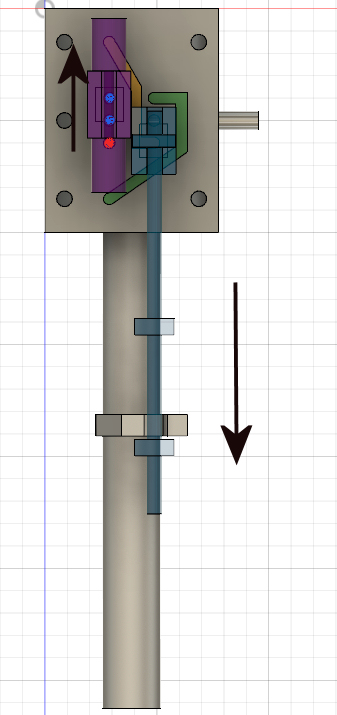
In this image, the piston has moved down to the bottom end, and the arm from the piston rod has hit the lower stopper on the valve rod, pushing it down. That has exposed the top hole above the right slider, which opens the passageway in green to steam, and the yellow passage to the exhaust. That makes the shuttle slider on the left (in purple) snap up to the top position, which exposes the lower left hole (red) to steam, and the other two ports to exhaust (blue). That will send steam to the bottom of the cylinder, and expose the top of the cylinder to exhaust, which will make the piston start moving back in the upwards direction.
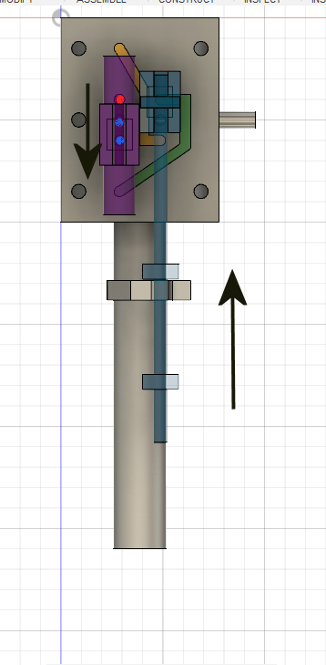
Once the piston gets near the top of the cylinder, we get this state: The arm on the piston rod has hit the upper stopper, which moves the valve rod upwards, exposing the lower right hole and its passage (in yellow) to steam, and the green passage to exhaust. That will send the shuttle (purple) down, which exposes the upper left port (now red) to steam, sending steam to the top of the cylinder. The other two ports (blue) are connected to exhaust and the lower end of the cylinder. This will cause the piston to start back up, and towards the state shown in the first picture again. And around it goes!
Quite a slick setup, all that movement with no crankshaft or eccentrics! I am impressed with their design.
One caveat - this is all for the 3" pump plans. In the other plans that Chipmaster showed for the 6" pump, it appears that the passages are different. I'll let someone else figure that one out, this one was enough for me!!


