Thank you Zephyrin for the kind comment!
The next part Ill be making is what I call the cylinder block. The challenge on this part will be the O-Ring groove and the cavity for the liquid cooling. The first picture is a sectioned rendering to illustrate how the finished part should look.

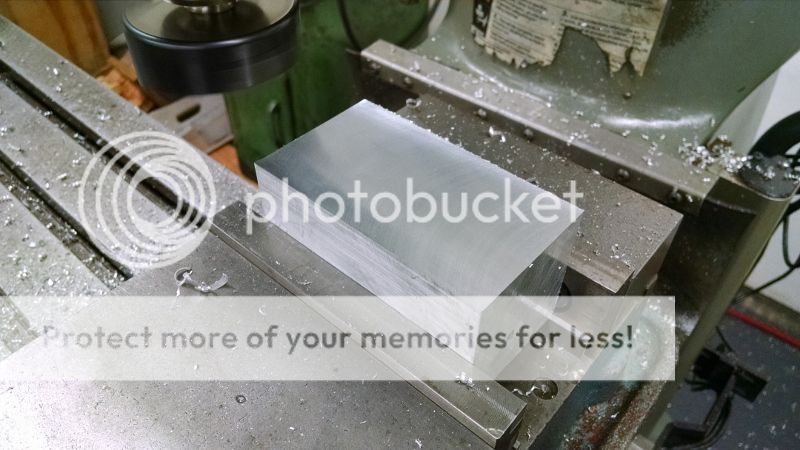
I started with squaring the block on 5 sides on the Bridgeport.
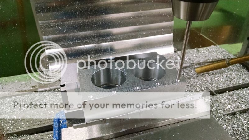
I then moved the work over to the CNC mill where the top side was faced over and two holes for the bores were pre-drilled. To rough out the two bores I used a long end mill and a helical interpolation. This is by no means the most efficient way when it comes to metal removal rate but it works very well with the long end mill. Another benefit is that it will produce the right size bore so its not going to take many passes with the boring head to get it to size.
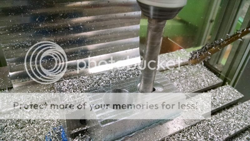
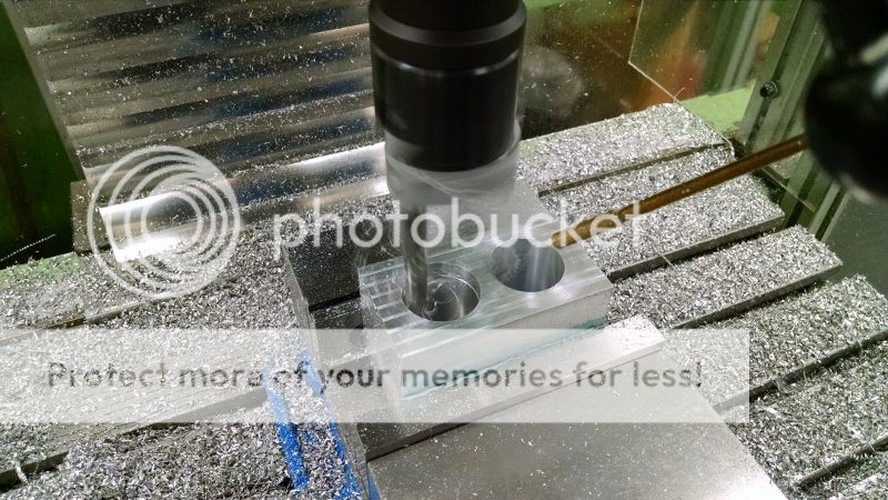
And bored out to finish size using a boring head.
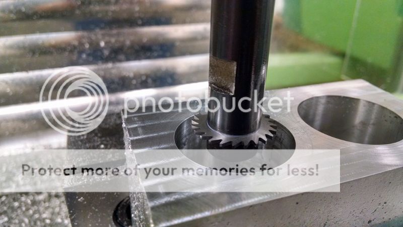
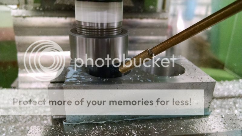
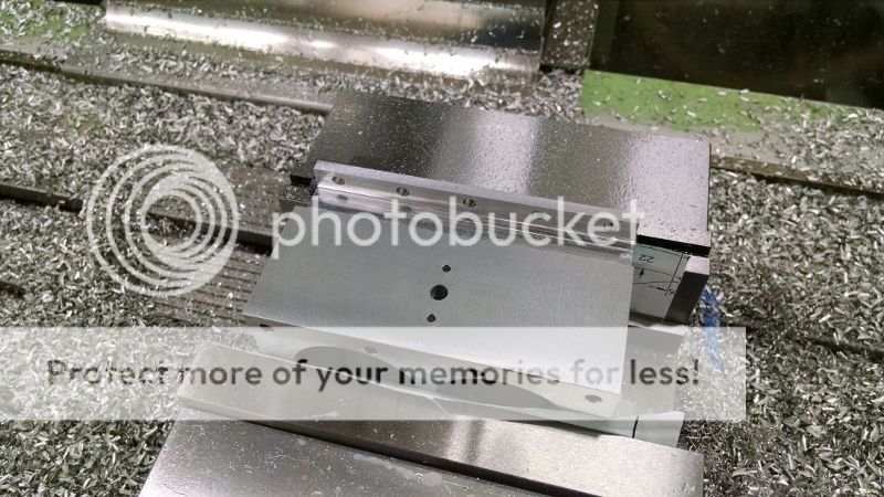
For the O-Ring groove I used a small slitting saw. The saw is 1 x 0.043
The groove is quite deep down in the bore making it a bit nerve wracking as its impossible to see the cut. Its one of those lets hope the code is right moments
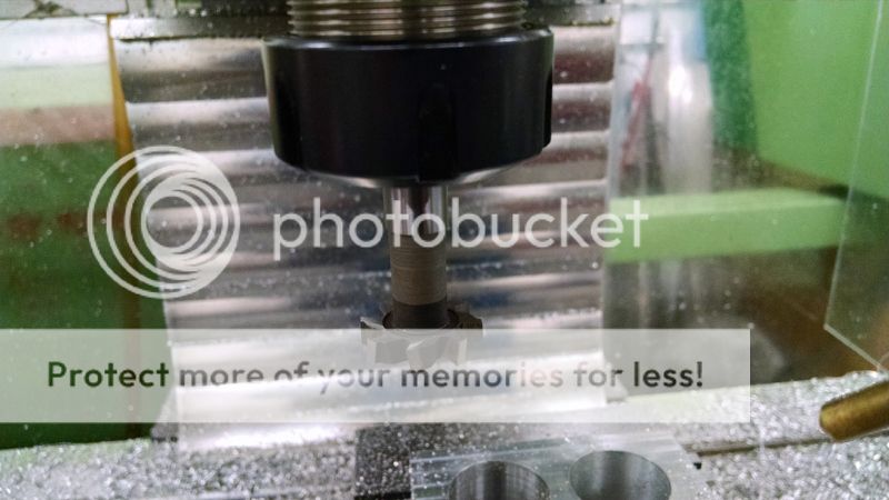
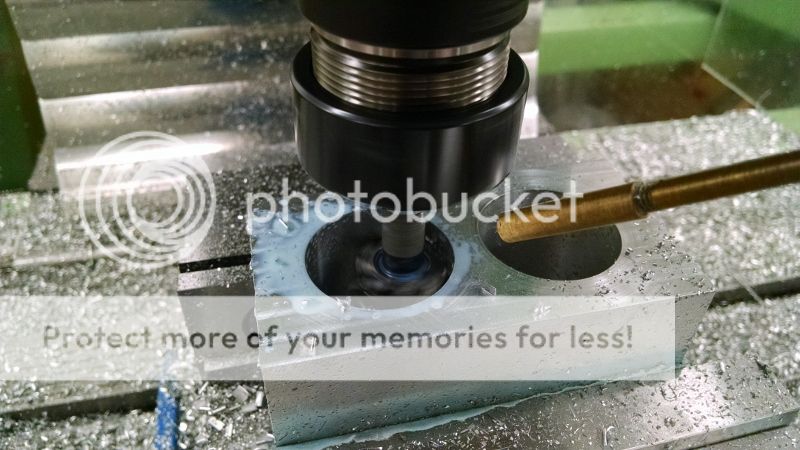
To relief the block for the coolant I used a T-slot cutter.

The next operation was to mill a step to seat the sleeve.

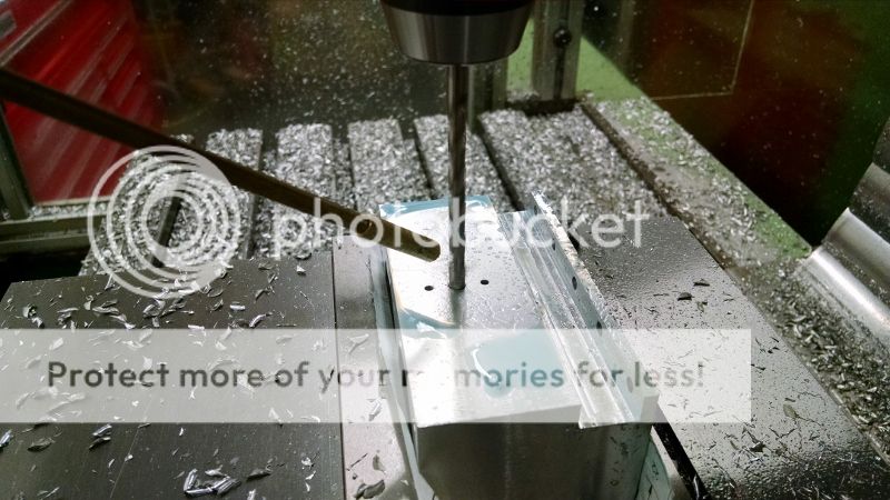
The last operation on the top of the block was to drill the holes for the cylinder head and coolant passages.
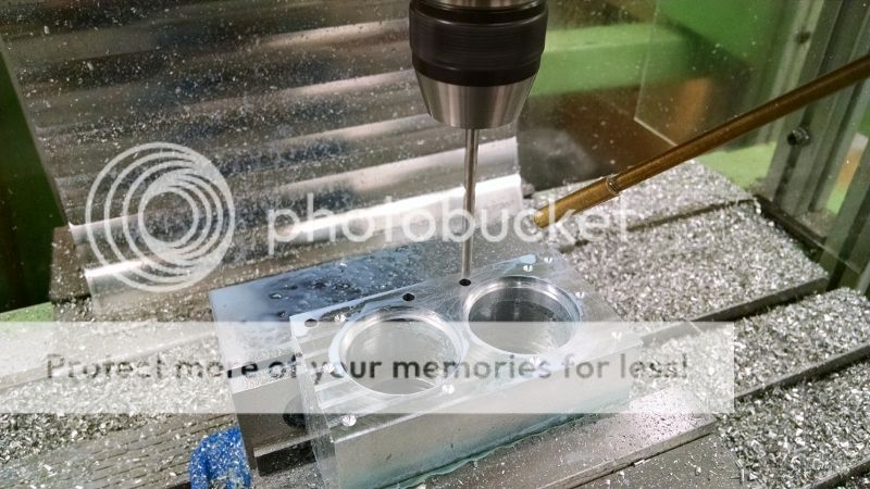
To top side finished:

The block is then turned over to drill the mounting holes at the bottom.
The bottom flange is milled.
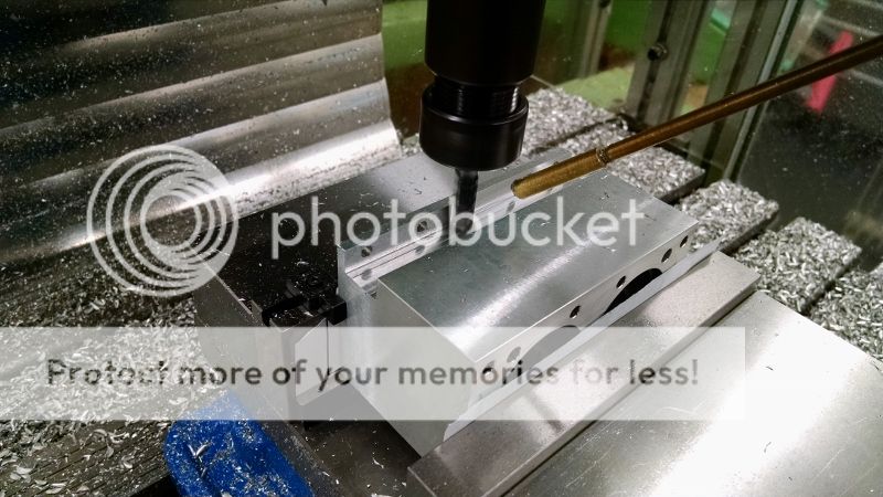
And the passage for the coolant inlet is drilled.
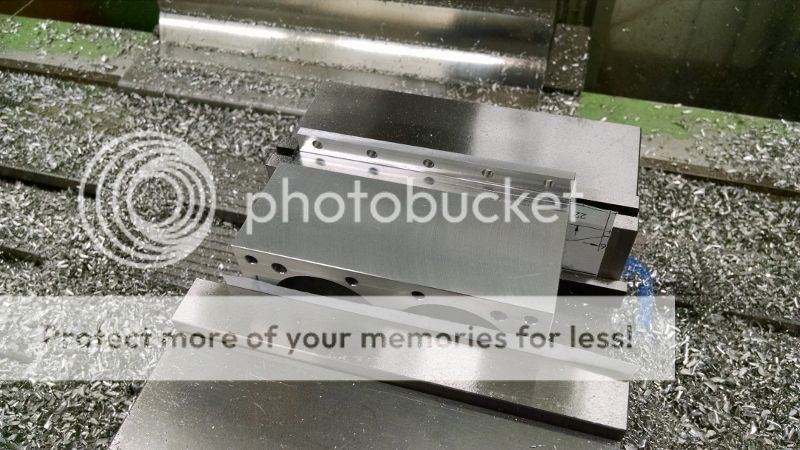
Last, the step on the sides were milled. This is a cosmetic feature as I needed a bit more length on the cylinder head but didn't want to lengthen the crankcase.

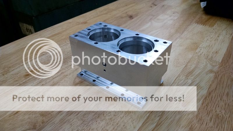
The finished cylinder block.
The engine is taking shape:

Stay tuned,
Yogi


