Author Topic: Freelance Inline Twin  (Read 53279 times)

Offline yogi

  • Full Member
  • ****
  • Posts: 450
  • Duncannon, PA USA
    • Yogi's Workshop
Re: Freelance Inline Twin
« Reply #45 on: December 13, 2016, 10:43:42 PM »
Thanks everyone for the kind comments. Much appreciated!  :cheers:

Per, the bearings are 61810  50x65x7 mm


Regards,
Yogi


Offline Dave Otto

  • Full Member
  • *****
  • Posts: 4704
  • Boise, Idaho USA
    • Photo Bucket
Re: Freelance Inline Twin
« Reply #46 on: December 13, 2016, 11:29:29 PM »
Very nice work on everything so far Yogi!
Were the crank pins pressed in place?

Dave

Offline b.lindsey

  • Global Moderator
  • Full Member
  • *****
  • Posts: 13860
  • Dallas, NC, USA
    • Workbench-Miniatures
Re: Freelance Inline Twin
« Reply #47 on: December 14, 2016, 02:29:49 AM »
Not to repeat but simply beautiful work Yogi!!  Still following along intently here.

Bill

Offline Art K

  • Full Member
  • ****
  • Posts: 1765
  • Madison, Wisconsin USA
Re: Freelance Inline Twin
« Reply #48 on: December 14, 2016, 04:21:38 AM »
Yogi,
This is looking very impressive. If I understand the crank construction correctly Dave the outer part of the web encloses the pin and locks it in place. The only way out is removing the bolts that hold the two halves of the web together. Yogi will there be any lubrication system?
Art
"The beautiful thing about learning is that no one can take it away from you" B.B. King

Offline yogi

  • Full Member
  • ****
  • Posts: 450
  • Duncannon, PA USA
    • Yogi's Workshop
Re: Freelance Inline Twin
« Reply #49 on: December 14, 2016, 07:09:28 AM »
Thanks for the comments guys!  :cheers:

Dave, the original idea was to use Loctite for the pins, but the fit turned out so well (a very light push fit) that I think it doesn't need it.

Art, you are correct, the pin can't go anywhere, as it is locked axial in place. I did have some concerns about the bending forces that might work on the crank pin, hence the Loctite for additional insurance. Now that I hold the crank in my hands, and can feel how solid it is, my gut feeling is that I will be working just fine the way it is.
It will be splash lubricated.

Yogi

Offline Zephyrin

  • Full Member
  • ****
  • Posts: 769
  • near Paris, France
Re: Freelance Inline Twin
« Reply #50 on: December 14, 2016, 08:14:03 AM »
Great work with this crankshaft, impressive and inspiring for model engine builders !

Offline yogi

  • Full Member
  • ****
  • Posts: 450
  • Duncannon, PA USA
    • Yogi's Workshop
Re: Freelance Inline Twin
« Reply #51 on: January 06, 2017, 03:41:58 AM »
Thank you Zephyrin for the kind comment!

The next part I’ll be making is what I call the cylinder block. The challenge on this part will be the O-Ring groove and the cavity for the liquid cooling. The first picture is a sectioned rendering to illustrate how the finished part should look.


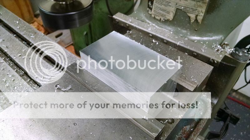
I started with squaring the block on 5 sides on the Bridgeport.


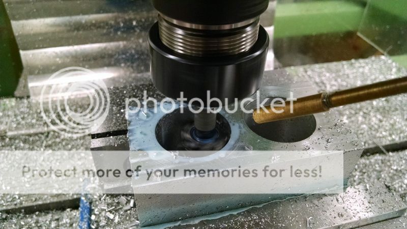
I then moved the work over to the CNC mill where the top side was faced over and two holes for the bores were pre-drilled. To rough out the two bores I used a long end mill and a helical interpolation. This is by no means the most efficient way when it comes to metal removal rate but it works very well with the long end mill. Another benefit is that it will produce the right size bore so it’s not going to take many passes with the boring head to get it to size.
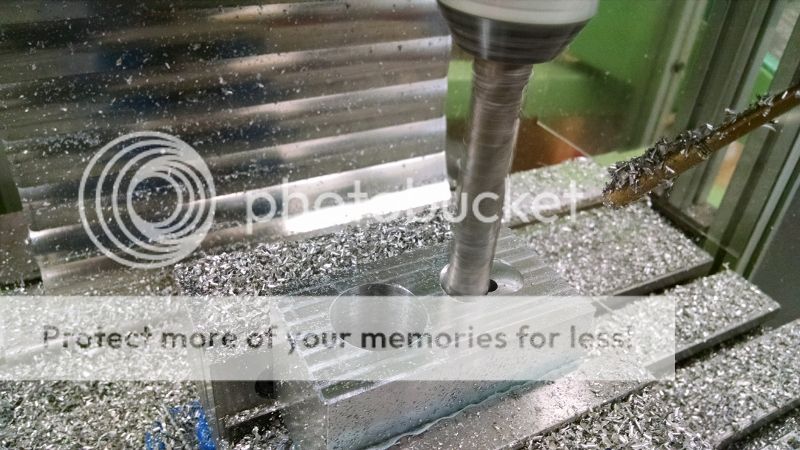


And bored out to finish size using a boring head.
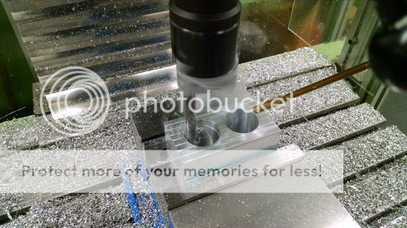


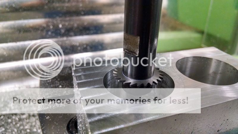
For the O-Ring groove I used a small slitting saw. The saw is 1 x 0.043”
The groove is quite deep down in the bore making it a bit nerve wracking as it’s impossible to see the cut. It’s one of those “let’s hope the code is right” moments…
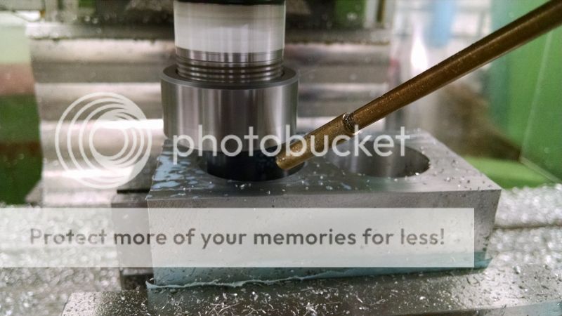


To relief the block for the coolant I used a T-slot cutter.
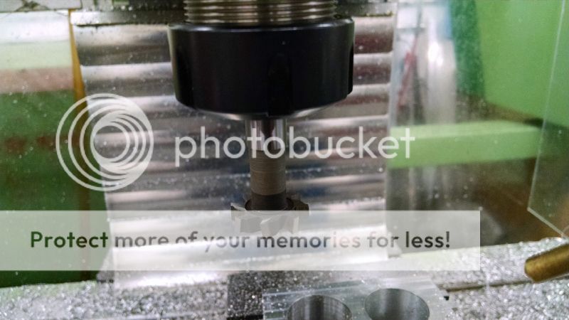


The next operation was to mill a step to seat the sleeve.


The last operation on the top of the block was to drill the holes for the cylinder head and coolant passages.
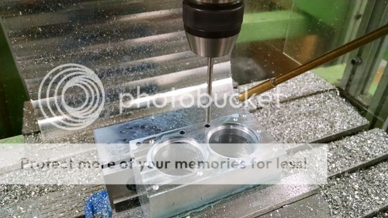


To top side finished:


The block is then turned over to drill the mounting holes at the bottom.
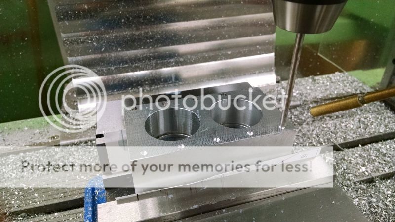


The bottom “flange” is milled.
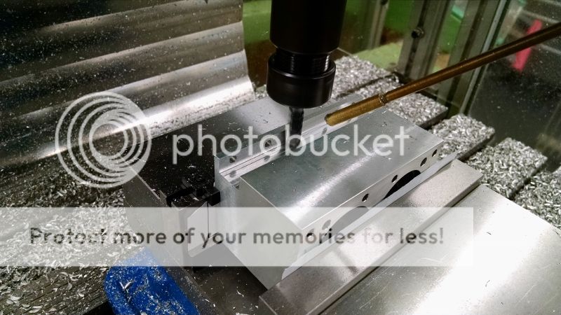


And the passage for the coolant inlet is drilled.
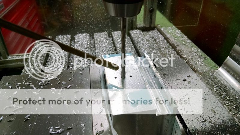


Last, the step on the sides were milled. This is a cosmetic feature as I needed a bit more length on the cylinder head but didn't want to lengthen the crankcase.


The finished cylinder block.
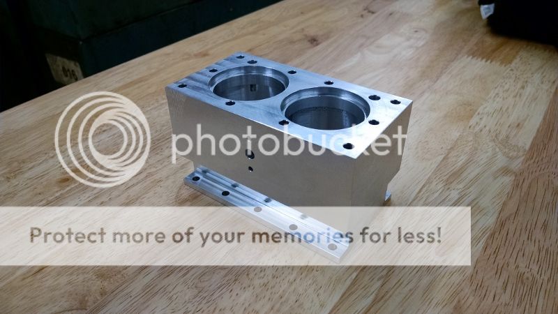


The engine is taking shape:


Stay tuned,
Yogi


Offline Roger B

  • Global Moderator
  • Full Member
  • *****
  • Posts: 6162
  • Switzerland
Re: Freelance Inline Twin
« Reply #52 on: January 06, 2017, 08:09:37 AM »
Excellent  :praise2:  :praise2: I need to look further into using a slot cutter for maching out the water spaces although I will have to use Steve Huck's manual version  ::)
Best regards

Roger

Offline stevehuckss396

  • Full Member
  • ****
  • Posts: 1554
  • Sterling Heights, MI USA
    • Steve's Miniature Sparkplugs
Re: Freelance Inline Twin
« Reply #53 on: January 06, 2017, 05:17:34 PM »
Really nice looking engine.  Great job man!
Do not be like the cat who wanted a fish but was afraid to get his paws wet.

Offline Dave Otto

  • Full Member
  • *****
  • Posts: 4704
  • Boise, Idaho USA
    • Photo Bucket
Re: Freelance Inline Twin
« Reply #54 on: January 07, 2017, 01:40:35 AM »
The cylinder block looks great Yogi.
The family shot also looks very nice!


Dave

Offline cfellows

  • Rest In Peace
  • Full Member
  • *
  • Posts: 1700
Re: Freelance Inline Twin
« Reply #55 on: January 07, 2017, 06:47:01 PM »
Really nice machine work!  The design looks great, too!

Chuck
So many projects, so little time...

Offline b.lindsey

  • Global Moderator
  • Full Member
  • *****
  • Posts: 13860
  • Dallas, NC, USA
    • Workbench-Miniatures
Re: Freelance Inline Twin
« Reply #56 on: January 07, 2017, 04:55:58 PM »
Fine looking engine Yogi.  Looking forward to your continued progress !

Bill

Offline yogi

  • Full Member
  • ****
  • Posts: 450
  • Duncannon, PA USA
    • Yogi's Workshop
Re: Freelance Inline Twin
« Reply #57 on: February 04, 2017, 04:46:29 AM »
Thanks everyone for the kind comments. It’s much appreciated!

The next part for the engine will be the covers to finish the crankcase. I’ll let the pictures do the talking rather than me trying to explain the steps, so please feel free to ask any questions if I leave anything out.

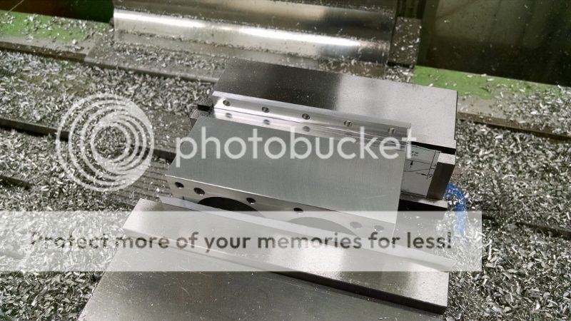
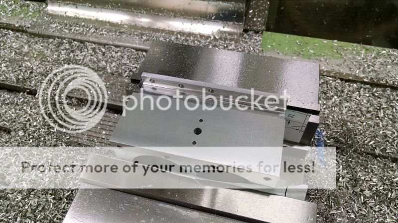
The front cover (accessory end) is milled on the CNC mill.
First, face milling the top:


Spotting and drilling the hole pattern:


Roughing the contour:


Milling the counter bores:


Finishing pass:


And an edge break around the contour with the spot drill:


First side finished:


I decided to make the gear cover as well, as I can use the same tools and similar set ups.
Again, first step was a face cut:


Spotting and drilling:


Roughing:


Milling the relief for the screw heads:


Finishing pass:


Edge break:


First side of the gear cover done:


A set of machinable soft jaws were installed in the vise and milled out for the second side operation.


Second side of the cover finished, still in the vise:


Another pocket in the soft jaws was milled out to finish the second side of the gear cover.


The finished parts:


Stay tuned…


Offline stevehuckss396

  • Full Member
  • ****
  • Posts: 1554
  • Sterling Heights, MI USA
    • Steve's Miniature Sparkplugs
Re: Freelance Inline Twin
« Reply #58 on: February 04, 2017, 12:21:29 PM »
Very nice!  The gear case looks a little bare. Maybe you could engrave something on it like a logo of some kind or the name of the engine when you figure it out.
Do not be like the cat who wanted a fish but was afraid to get his paws wet.

Offline zeeprogrammer

  • Full Member
  • *****
  • Posts: 6811
  • West Chester, PA, USA
Re: Freelance Inline Twin
« Reply #59 on: February 04, 2017, 01:47:24 PM »
Awesome project yogi and the parts look fantastic!

It may have been asked before...tell me about your cooling system on the mill.
Carl (aka Zee) Will sometimes respond to 'hey' but never 'hey you'.
"To work. To work."
Zee-Another Thread Trasher.


SimplePortal 2.3.5 © 2008-2012, SimplePortal