Author Topic: Four Valve Non-Releasing Steam Engine  (Read 90394 times)

Offline steamer

  • Global Moderator
  • Full Member
  • *****
  • Posts: 12699
  • Central Massachusetts, USA
Re: Four Valve Non-Releasing Steam Engine
« Reply #30 on: September 14, 2012, 02:05:51 AM »
I love it Jerry!  It looks really nice and scale...without being too fussy!   NICE!

Dave
"Mister M'Andrew, don't you think steam spoils romance at sea?"
Damned ijjit!

Offline NickG

  • Global Moderator
  • Full Member
  • *****
  • Posts: 1430
Re: Four Valve Non-Releasing Steam Engine
« Reply #31 on: September 14, 2012, 01:24:26 PM »
I was going to ask whether you had plans to leave the cap screws ... then read the final sentence!  :ThumbsUp:

Offline Bearcar1

  • Full Member
  • ****
  • Posts: 829
  • Chicagoland Area, USA
Re: Four Valve Non-Releasing Steam Engine
« Reply #32 on: September 14, 2012, 04:21:37 PM »
Looks like a majestic beast for certain, Jerry. I'm following along with a keen interest.  :ThumbsUp: :ThumbsUp:


BC1
Jim

Offline Captain Jerry

  • Full Member
  • ****
  • Posts: 1073
  • Summerfield, FL USA
Re: Four Valve Non-Releasing Steam Engine
« Reply #33 on: September 18, 2012, 04:19:39 AM »
I made a little progress today.  My shop time has been severely limited this week.  My 3 yr old great-grand-daughter has been spending a lot of time here and she is a lot more fun, seriously!  It's been a hell of a long time since I was 3 years old and I am sure that I didn't have the level of sophistication that she has.  It may be that I didn't have TV when I was her age or It may be that I didn't have a great-grand-father.

Because my shop time is so limited and because I feel some pressure (self imposed) to get this engine running, I have been working faster and taking fewer pictures.  And, I am no longer working from plans.  I am working from a mental picture and make-fit procedures.  I hope I don't lose your interest but I want to get to the heart of this build, the valves, where I will take a little more time.

Today's part is the outboard bearing.  The critical dimensions are accurately fitted.  It needs profiling of the vertical edges for esthetic improvement, but functionally, it provides shaft support so that I can refine the working relationship of the moving parts.

Here is the part


and here are the moving parts moving.


I am going to stick with the small flywheel at this stage, until I have worked out the alignment of the eccentric and the wrist plate and also the space required for a governor drive pulley.  After that, I can pierce the deck for a larger flywheel and fix the final position for the outboard bearing.

Jerry

NOTARY SOJAK

There are things that you can do and some things you can't do. Don't worry about it. try it anyway.

Offline arnoldb

  • Administrator
  • Full Member
  • *****
  • Posts: 1341
  • Windhoek, Namibia
Re: Four Valve Non-Releasing Steam Engine
« Reply #34 on: September 18, 2012, 07:29:56 AM »
It's coming along nicely Jerry.  You're right, the valves and the timing will be the most interesting part.

Kind regards, Arnold
Building an engine takes Patience, Planning, Preparation and Machining.
Procrastination is nearly the same, but it precludes machining.
Thus, an engine will only be built once the procrastination stops and the machining begins!

Offline Maryak

  • Rest In Peace
  • Full Member
  • *
  • Posts: 1818
  • Aldinga Beach South Australia
Re: Four Valve Non-Releasing Steam Engine
« Reply #35 on: September 18, 2012, 08:00:29 AM »
Nice work CJ,  :NotWorthy:

Looks like you proportioned the flywheel pretty well.  :NotWorthy:

Best Regards
Bob
Если вы у Тетушки были яйца, она была бы Дядюшкой

Offline swilliams

  • Full Member
  • ****
  • Posts: 896
  • Canberra Australia
Re: Four Valve Non-Releasing Steam Engine
« Reply #36 on: September 18, 2012, 12:02:55 PM »
I like the approach Jerry, the valves are going to be very interesting. It's looking good

Steve

Offline Captain Jerry

  • Full Member
  • ****
  • Posts: 1073
  • Summerfield, FL USA
Re: Four Valve Non-Releasing Steam Engine
« Reply #37 on: September 24, 2012, 10:35:11 PM »
Progress has been intermittent. Here is a little update.

The crank case bed is bolted to the base but the outboard bearing is just there for fun, waiting for eccentric and governor pulley to be fitted.  The base is an aluminum plate that is covered with paper and tape to prevent scratches.

I have my big brass baton on the end of the shaft to provide rotation so I can check clearance and it turns very freely,


>>>>> VIDEO <<<<<


I got cranking and turning and then I had an idea :noidea:


VVVVVV  MORE VIDEO VVVVVVV


HOW ABOUT THAT! 


Jerry
« Last Edit: January 24, 2013, 12:29:21 AM by Captain Jerry »
NOTARY SOJAK

There are things that you can do and some things you can't do. Don't worry about it. try it anyway.

Offline zeeprogrammer

  • Full Member
  • *****
  • Posts: 6811
  • West Chester, PA, USA
Re: Four Valve Non-Releasing Steam Engine
« Reply #38 on: September 24, 2012, 11:21:42 PM »
HOW ABOUT THAT! 

Pretty COOL!

Looks and sounds like very good action. It's going to be a very good engine.
Carl (aka Zee) Will sometimes respond to 'hey' but never 'hey you'.
"To work. To work."
Zee-Another Thread Trasher.

Offline tvoght

  • Full Member
  • ****
  • Posts: 1003
  • Indiana
Re: Four Valve Non-Releasing Steam Engine
« Reply #39 on: September 24, 2012, 11:46:38 PM »
I'm glad you showed that. I've been wondering for awhile why folk don't make finger engines more in that style.

--Tim

Offline steamer

  • Global Moderator
  • Full Member
  • *****
  • Posts: 12699
  • Central Massachusetts, USA
Re: Four Valve Non-Releasing Steam Engine
« Reply #40 on: September 25, 2012, 01:06:32 AM »
Its coming right along Jerry!   Keep it coming!

Dave
"Mister M'Andrew, don't you think steam spoils romance at sea?"
Damned ijjit!

Online Jo

  • Administrator
  • Full Member
  • *****
  • Posts: 15305
  • Hampshire, england.
Re: Four Valve Non-Releasing Steam Engine
« Reply #41 on: September 25, 2012, 07:36:42 AM »
Wow, you are moving along at some pace. Looking good :ThumbsUp:.

Jo
Enjoyment is more important than achievement.

Offline swilliams

  • Full Member
  • ****
  • Posts: 896
  • Canberra Australia
Re: Four Valve Non-Releasing Steam Engine
« Reply #42 on: September 26, 2012, 10:46:01 AM »
still watching with interest Jerry

Steve

Offline b.lindsey

  • Global Moderator
  • Full Member
  • *****
  • Posts: 13860
  • Dallas, NC, USA
    • Workbench-Miniatures
Re: Four Valve Non-Releasing Steam Engine
« Reply #43 on: September 26, 2012, 02:59:05 PM »
I hadn't checked in in a while Jerry. Lotos of progress I see too....and it all looks amazing. I very much like the flywheel proportions too as someone already noted.

Bill

Offline Captain Jerry

  • Full Member
  • ****
  • Posts: 1073
  • Summerfield, FL USA
Re: Four Valve Non-Releasing Steam Engine
« Reply #44 on: October 02, 2012, 04:10:07 AM »
When I started this project, I identified the biggest challenge for me would be the four small links that transfer motion from the wrist plate to the valve lever.   I think I could make one link with no problem.  The problem is that there are four of these little buggers and they are close together and therefore they all have to look the same.   This is the same kind of stuff that keeps me from trying a vertical engine with Stephenson reversing links.  Little bitty pieces that attract a lot of attention.

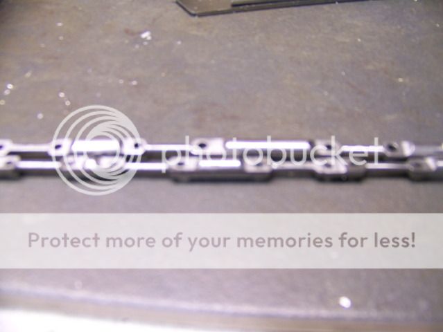
I now have a lot of experience making little links. I have made about two dozen of them now and I have identified about two dozen pitfalls to avoid.  But I am getting better.  And I have developed a method that has given me some repeatability.  This is what I want them to look like.
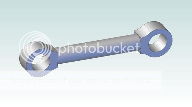


The holes are 3/32" dia spaced .600" and the center shaft is .080" OD and the transition filet has a .094 radius.  I have some 3/16" OD steel shaft so that is what I started with, first turning the center shaft to .080" using a 60 degree tool that leaves a beveled shoulder at each end.  I made four of these on each of two 4" lengths of shaft.  The turned section is .400" long.
.....
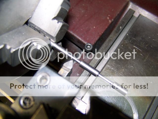


------
The next step is to clamp the workpiece in a pair of V-blocks held it the mill vice and locate the center on the Y axis.  The Y axis is then locked and will not be moved until all of the links are drilled and milled.
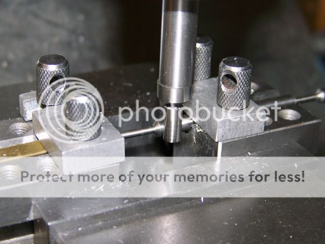


After that, the holes are spotted with a spotting drill and drilled 3/32".  I used the edge of the shoulders center the link and spaced the holes .600" apart.
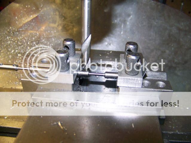


The bar is shifted in the V Blocks and all of the holes drilled without moving the V Blocks and without moving the Y axis.


The next step is to mill the link ends flat and to the same .080" thickness of the center shaft.  The rod is rotated 90? in the V block by using the drill bit and a couple of thin parallels resting on the vice jaws.
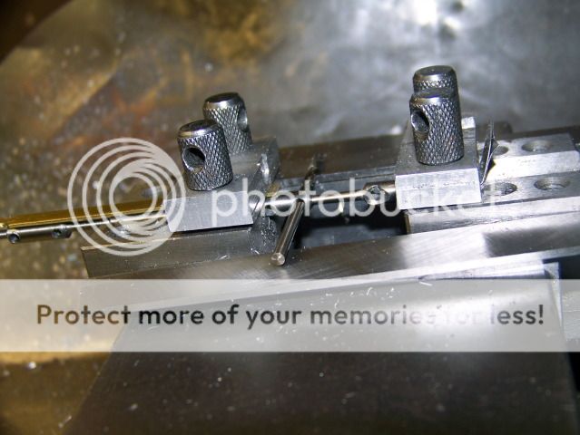


The mill is fitted with a 4 flute 3/16" end mill.  The mill is still on center so adding the mill diameter and the required shaft diameter and dividing by 2 ( .187" + .080") / 2 = .134" so the table is cranked back .134" and the end mill is brought down to test.  It just brushes the center shaft! Perfect.
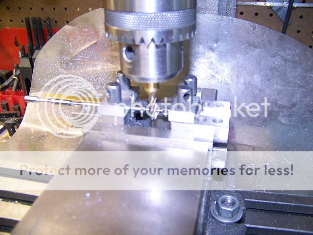


Cut to the right, cut to the right, and its half done.  On the cut to the left, it's climb milling, so I tightened up on the X gib to help control the cut.  No problems.



Now I need to cut the back side of the part.  I could move the table back in the Y direction, I know how far to go, but then I would have to move it back again for the next part.  Another way to do it is just open the vise, turn the part around with the V Blocks attached, and make the cut on the front.  Much better.  No table movement required as I finish all of the parts.  I didn't take a picture of this because it would look just like the previous picture.

Now I have a bunch of near parts on a rod.  Hacksaw time.  The only thing left is to round the ends.  In theory, there are many ways that this can be done.  I tried several of them.  I even built a special fixture and sacrificed a few parts to it.   This I firmly believe.  Any method that requires the part to be rotated on a fixed pivot will fail.  Even if you can find some way to hold the little bugger (my special fixture), if the part can be turned on the pivot,  there will be enough slop on the pivot that the cut will be uneven.  I have evidence of that.

I came to the conclusion that the part must be fitted on a mandrel with a tapered shoulder and held securely with a nut and a jamb nut!  I turned a piece of steel shaft to just a RCH over the 3/32" and then put a little taper on it with a file.  Then I threaded the end with about a 1/4" of #2-56 thread.  I have a supply of scale #2-56 nuts that are .125" across the flats.  I took some photos of this mandrel and how it is set up and used but they are so out of focus as to be unusable.  Sorry!  I promise to get some better pics tomorrow and I will continue this post then.

Thanks for watching.

Jerry


NOTARY SOJAK

There are things that you can do and some things you can't do. Don't worry about it. try it anyway.


SimplePortal 2.3.5 © 2008-2012, SimplePortal