When I started this project, I identified the biggest challenge for me would be the four small links that transfer motion from the wrist plate to the valve lever. I think I could make one link with no problem. The problem is that there are four of these little buggers and they are close together and therefore they all have to look the same. This is the same kind of stuff that keeps me from trying a vertical engine with Stephenson reversing links. Little bitty pieces that attract a lot of attention.
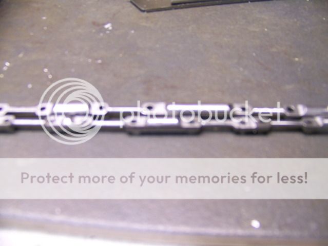
I now have a lot of experience making little links. I have made about two dozen of them now and I have identified about two dozen pitfalls to avoid. But I am getting better. And I have developed a method that has given me some repeatability. This is what I want them to look like.
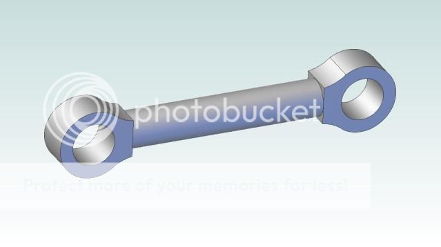
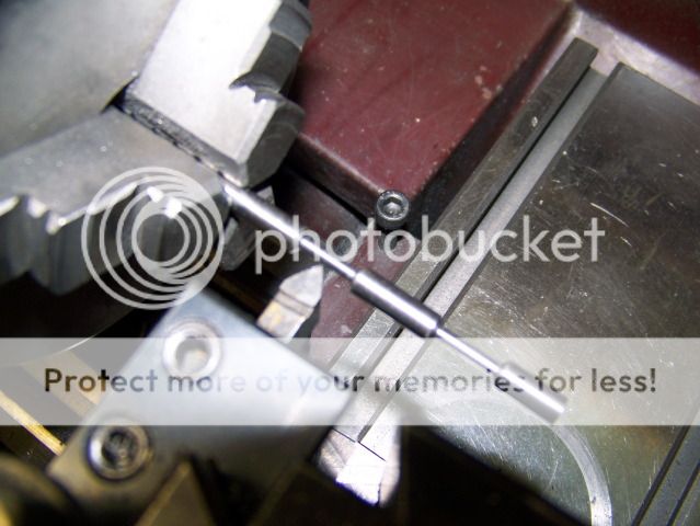
The holes are 3/32" dia spaced .600" and the center shaft is .080" OD and the transition filet has a .094 radius. I have some 3/16" OD steel shaft so that is what I started with, first turning the center shaft to .080" using a 60 degree tool that leaves a beveled shoulder at each end. I made four of these on each of two 4" lengths of shaft. The turned section is .400" long.
.....
------
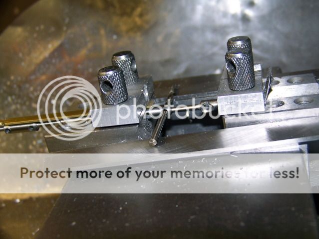
The next step is to clamp the workpiece in a pair of V-blocks held it the mill vice and locate the center on the Y axis. The Y axis is then locked and will not be moved until all of the links are drilled and milled.
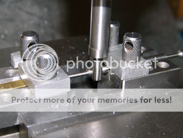
After that, the holes are spotted with a spotting drill and drilled 3/32". I used the edge of the shoulders center the link and spaced the holes .600" apart.
The bar is shifted in the V Blocks and all of the holes drilled without moving the V Blocks and without moving the Y axis.
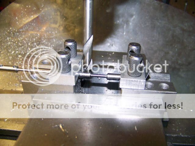
The next step is to mill the link ends flat and to the same .080" thickness of the center shaft. The rod is rotated 90? in the V block by using the drill bit and a couple of thin parallels resting on the vice jaws.
The mill is fitted with a 4 flute 3/16" end mill. The mill is still on center so adding the mill diameter and the required shaft diameter and dividing by 2 ( .187" + .080") / 2 = .134" so the table is cranked back .134" and the end mill is brought down to test. It just brushes the center shaft! Perfect.
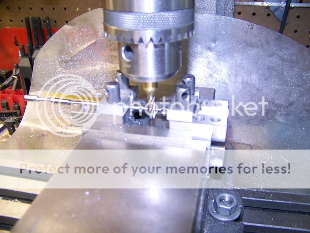
Cut to the right, cut to the right, and its half done. On the cut to the left, it's climb milling, so I tightened up on the X gib to help control the cut. No problems.

Now I need to cut the back side of the part. I could move the table back in the Y direction, I know how far to go, but then I would have to move it back again for the next part. Another way to do it is just open the vise, turn the part around with the V Blocks attached, and make the cut on the front. Much better. No table movement required as I finish all of the parts. I didn't take a picture of this because it would look just like the previous picture.
Now I have a bunch of near parts on a rod. Hacksaw time. The only thing left is to round the ends. In theory, there are many ways that this can be done. I tried several of them. I even built a special fixture and sacrificed a few parts to it. This I firmly believe. Any method that requires the part to be rotated on a fixed pivot will fail. Even if you can find some way to hold the little bugger (my special fixture), if the part can be turned on the pivot, there will be enough slop on the pivot that the cut will be uneven. I have evidence of that.
I came to the conclusion that the part must be fitted on a mandrel with a tapered shoulder and held securely with a nut and a jamb nut! I turned a piece of steel shaft to just a RCH over the 3/32" and then put a little taper on it with a file. Then I threaded the end with about a 1/4" of #2-56 thread. I have a supply of scale #2-56 nuts that are .125" across the flats. I took some photos of this mandrel and how it is set up and used but they are so out of focus as to be unusable. Sorry! I promise to get some better pics tomorrow and I will continue this post then.
Thanks for watching.
Jerry


