Thanks for the comments chaps.
The Allman differes from a lot of hit and miss engines by having it's governor weights inside the pully rather than the more common position on inside the flywheel.
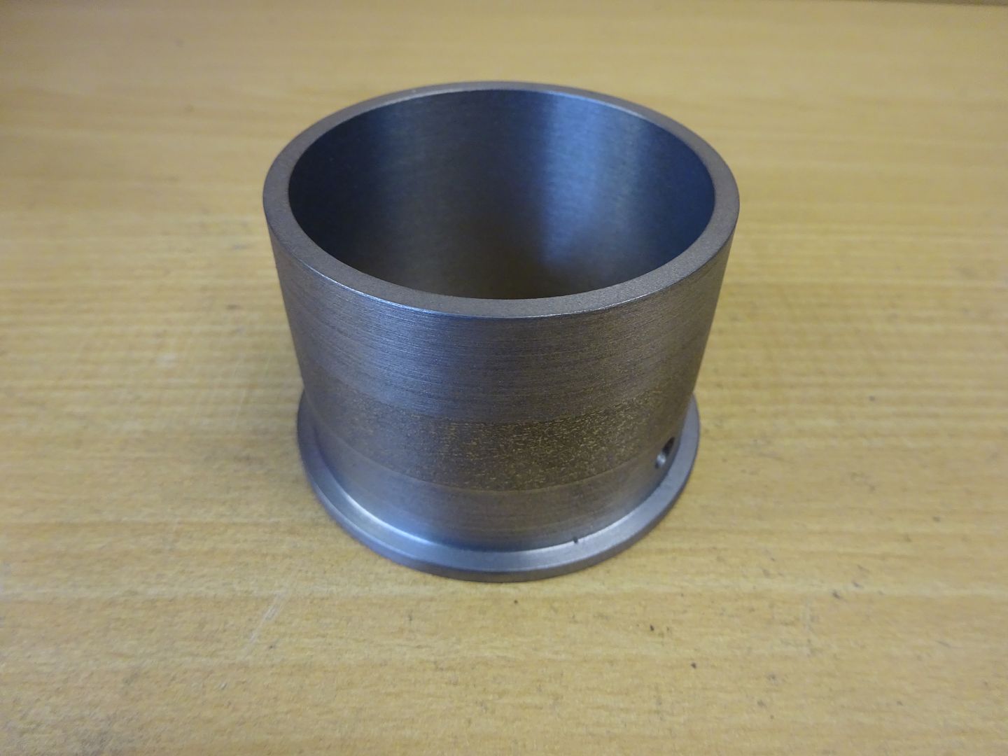
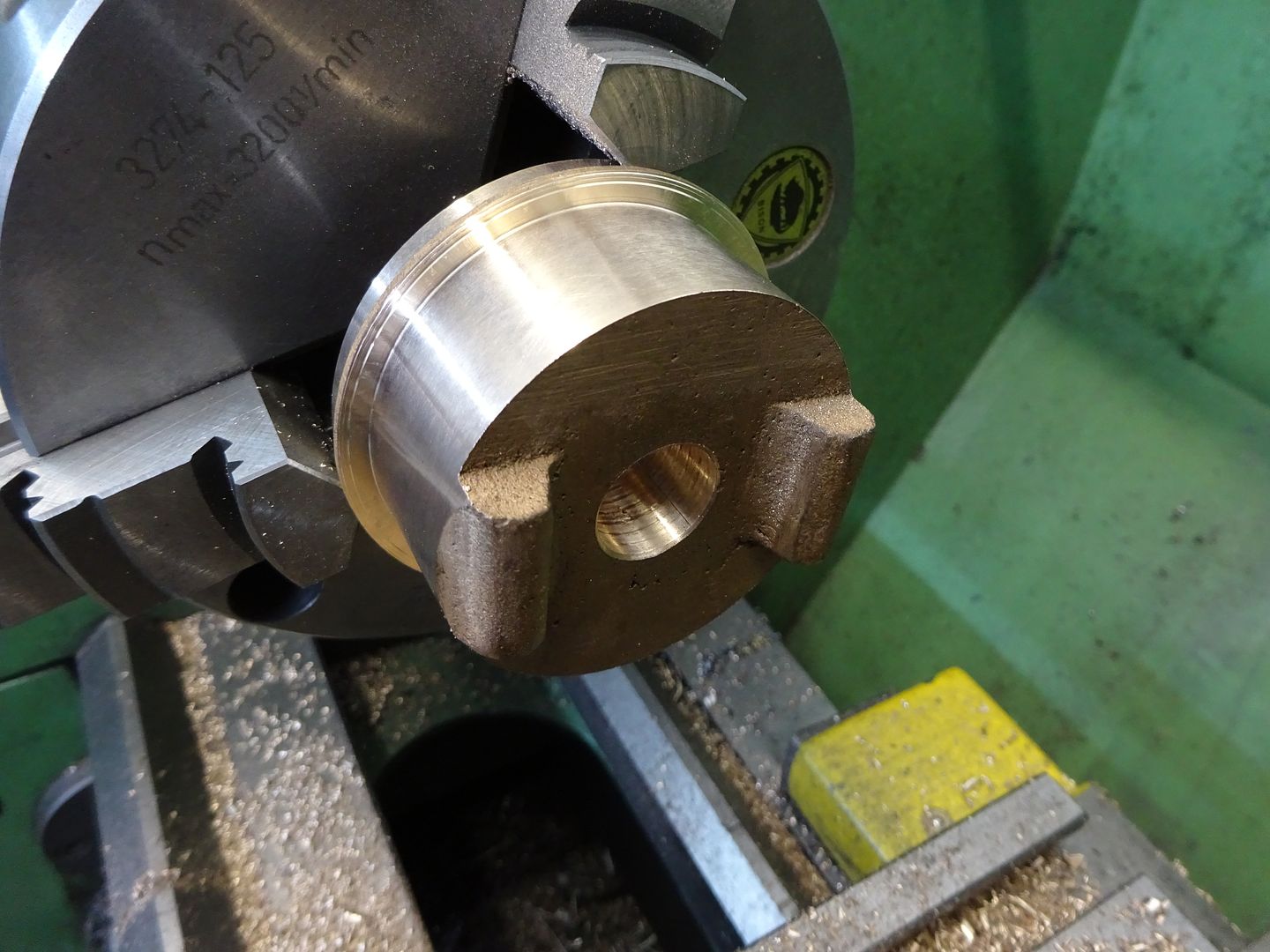
A piece of hollow CI bar is supplied for the pully. First job was to turn the outside diameter, you should be able to see three different bands on the surface this is where I have made two slightly tapered cuts either side of a centrall parallel section, these bands will get blended to form the crown of the pully later.
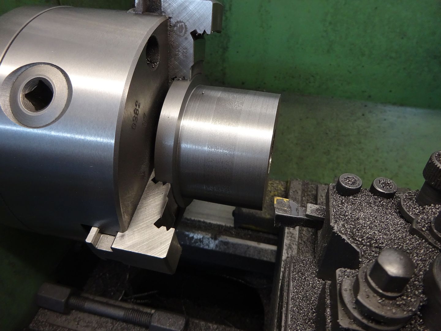
Next using a sturdy 16mm diameter boring bar the inside was opened out to the required 2.125" diameter. I placed the hold down stud and nuts on the bed to act as a carrage stop so I did not run the boring bar out the far end and into the chuck jaws.
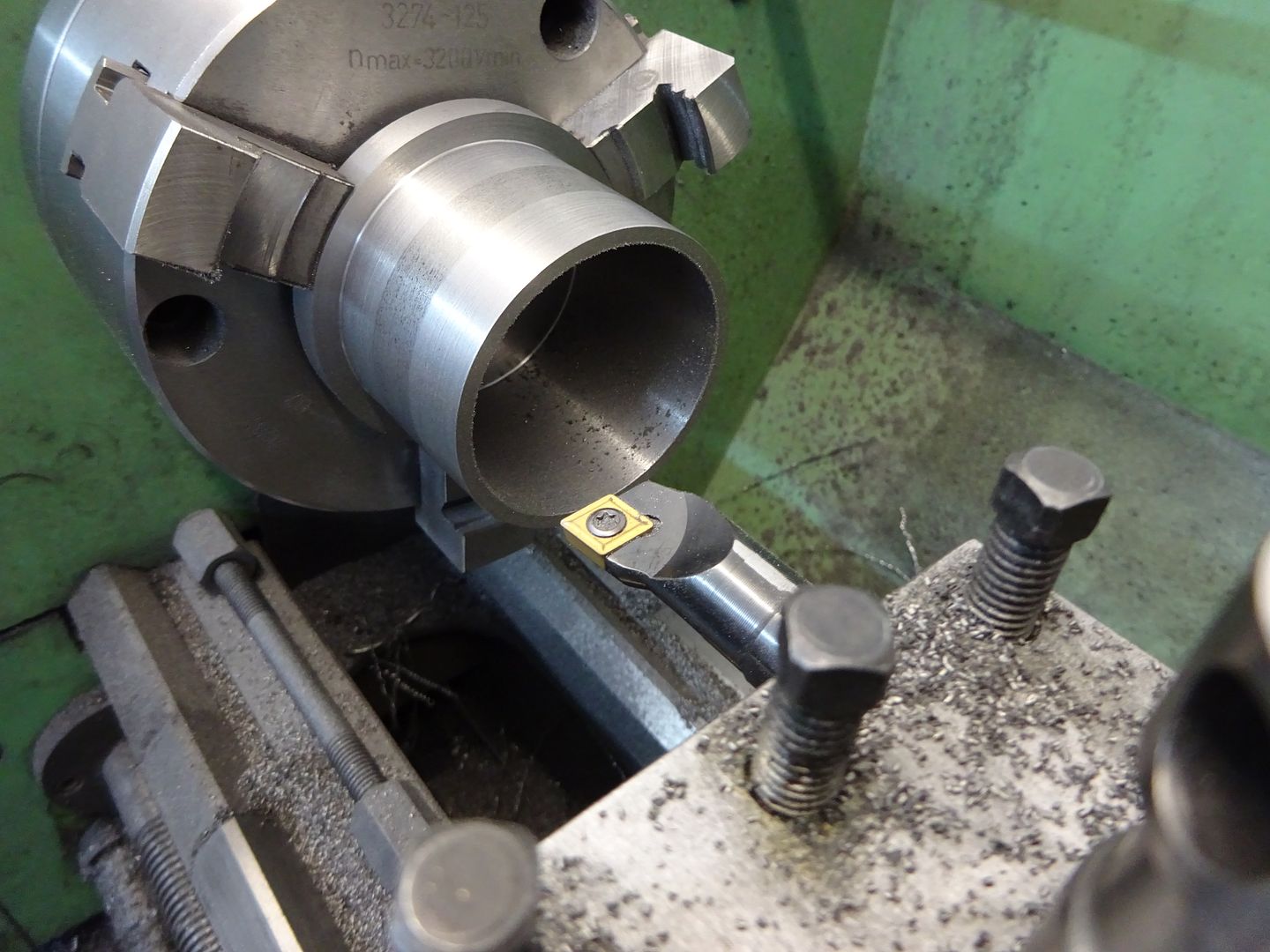
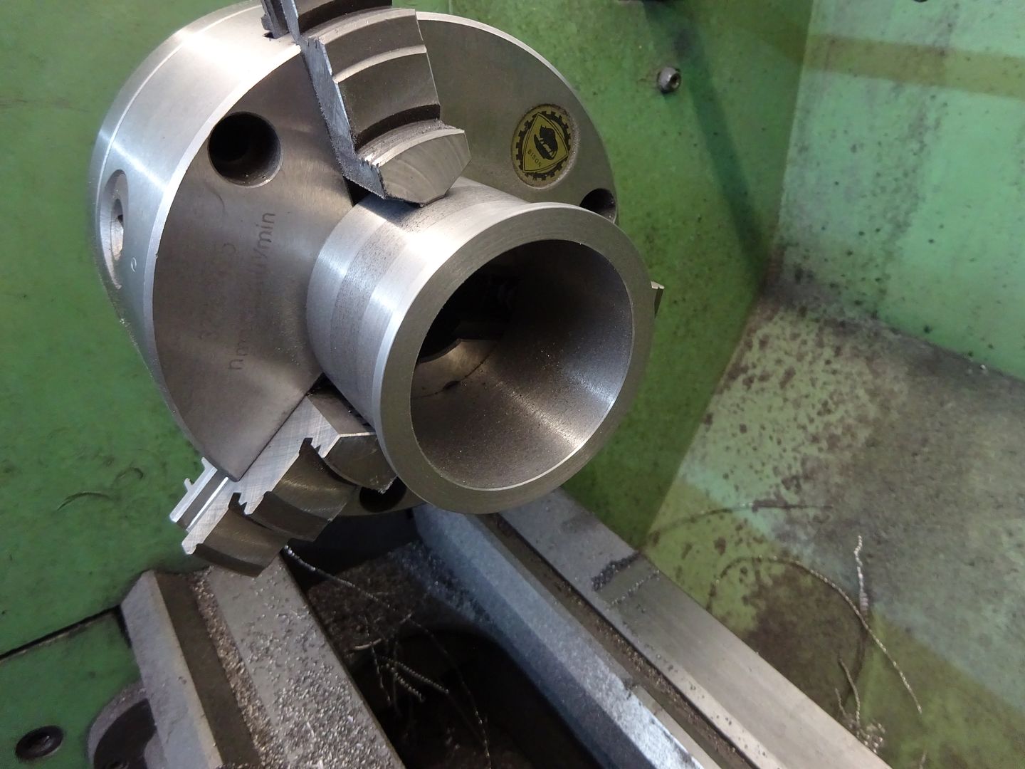
With that done the pully was reversed in the chuck and taken down to final length leaving a small flange at the end which stops any stray belts wandering into the timing gears.
Finally a clearance hole for a hex key was added.
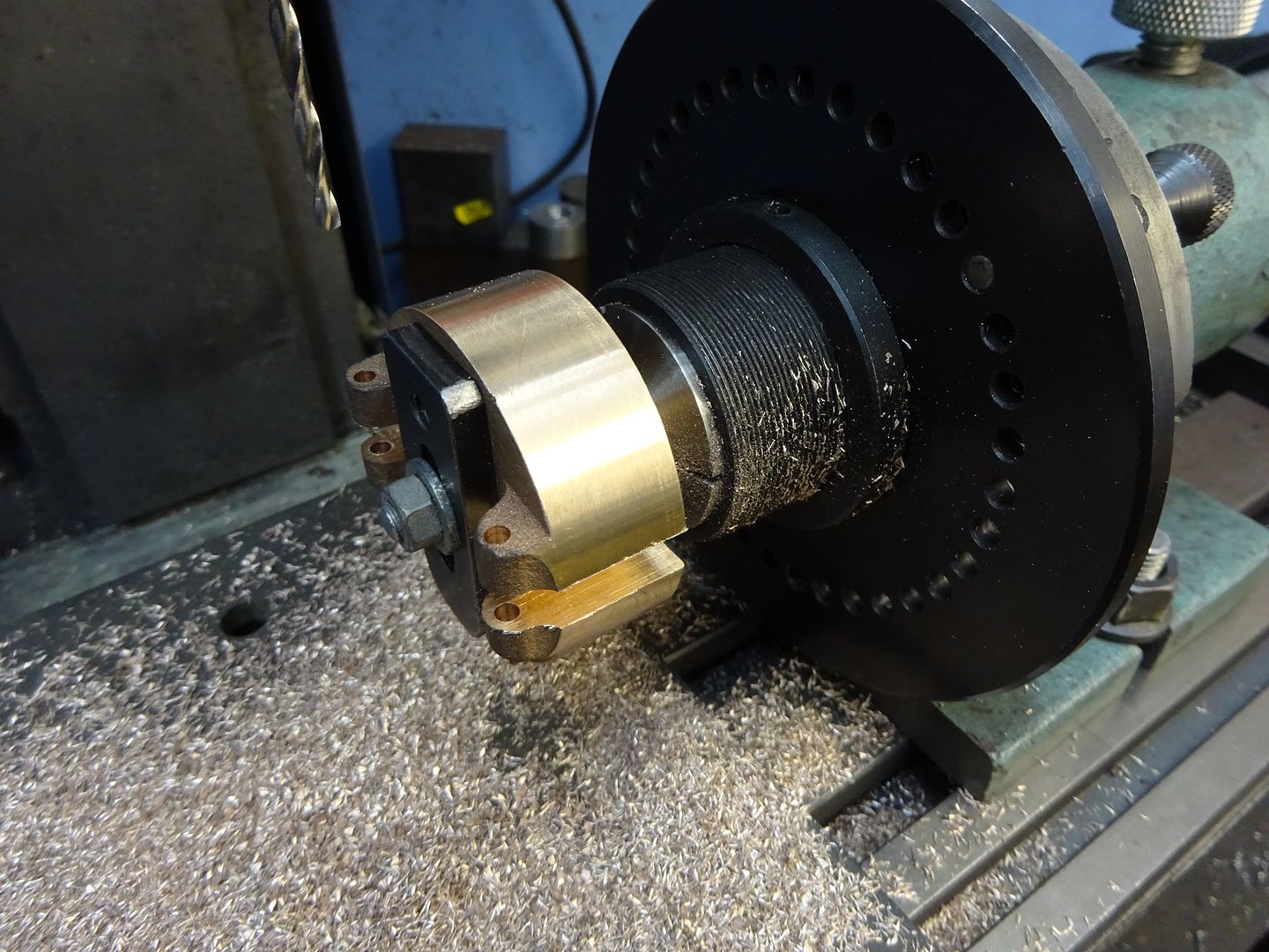
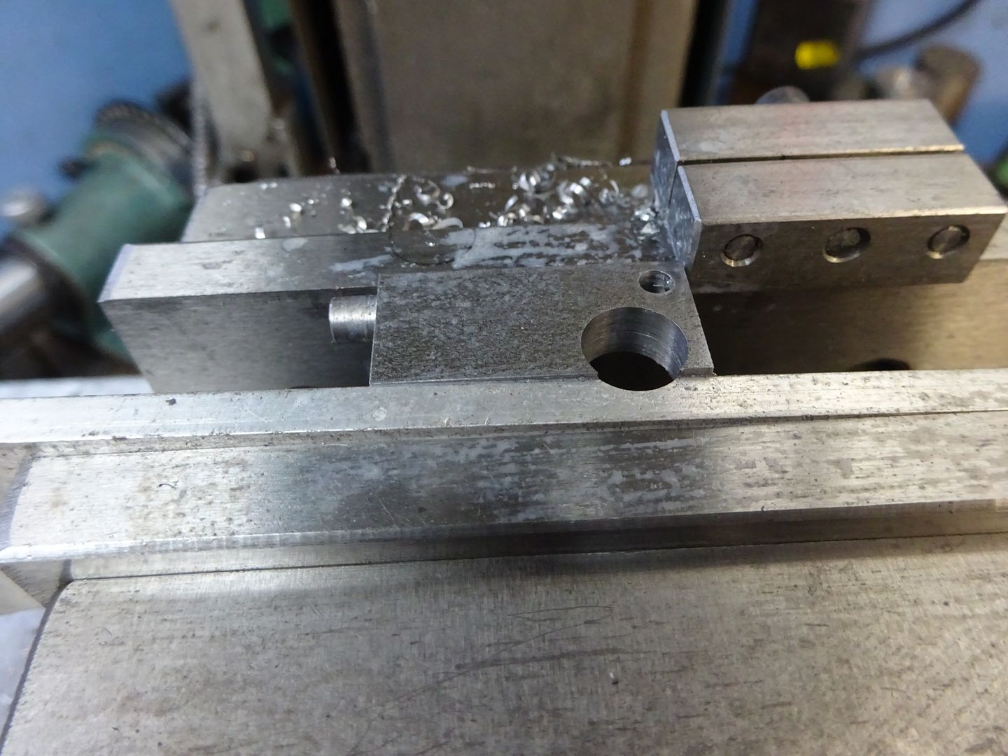
The governor arm bracket is very similar to a lot of others though quite a bit deeper. First thing to do was machine the outside for a press fit into the pully and then bore 5/8" for the crankshaft.
After facing the rear down to final length it's over to the mill and fix the bracket to a mandrel which could be held in the indexer. Mill the two slots for the governor arms and then rotate 90 degrees to drill & ream for the pivot pins.
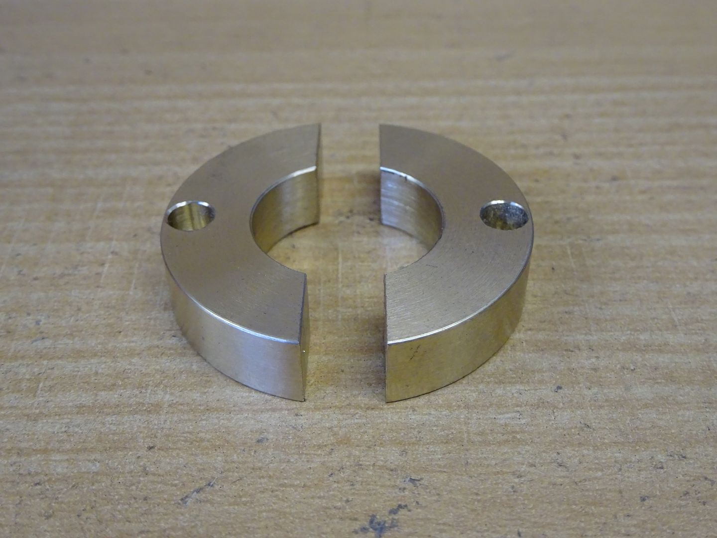
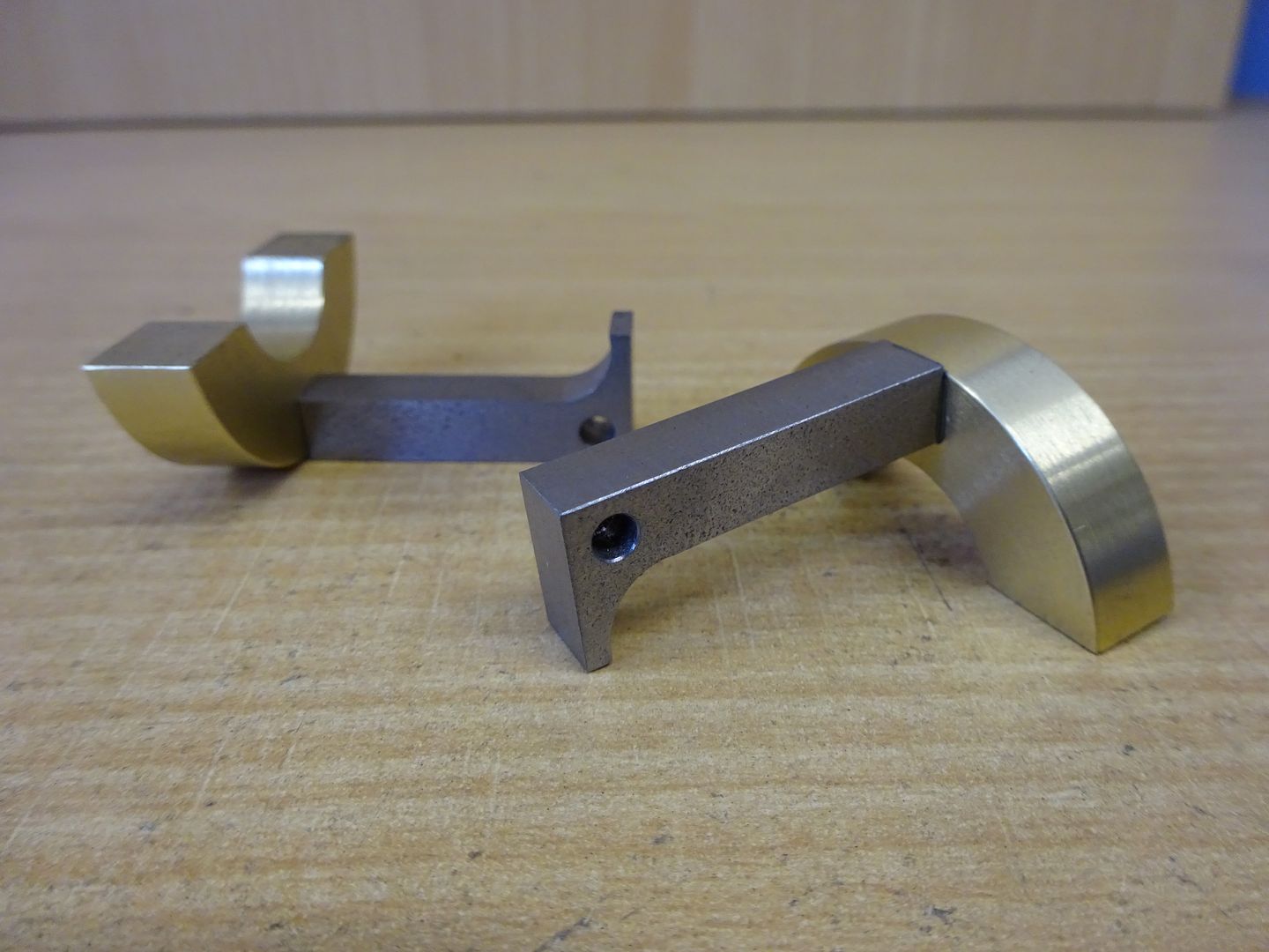
The two governor weights were turned from a slice of brass, cut in half and then a flat bottomed hole cut with a 2-flute milling cutter was added to press the arms into.
For the arms a bit of steel was milled upto size and the spigot that presses into the weight turned on either end.
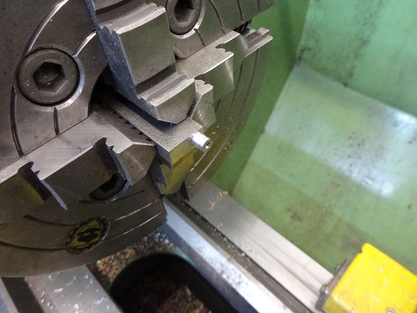
After cutting in half and milling to length the pivot hole was drilled & reamed and a larger hole added to form the inside curve of the arm. Note I have a piece of scrap aluminium to cut into rather than the vice jaw which is always preferable.
A bit more milling and filing and the arms could be pressed into the weights with a bit of loctite for good measure.
Once I had checked that the weights moved freely in their slots and broached a 3/16" keyway the bracket could be pressed into the pully, I used the mills quill to do this.
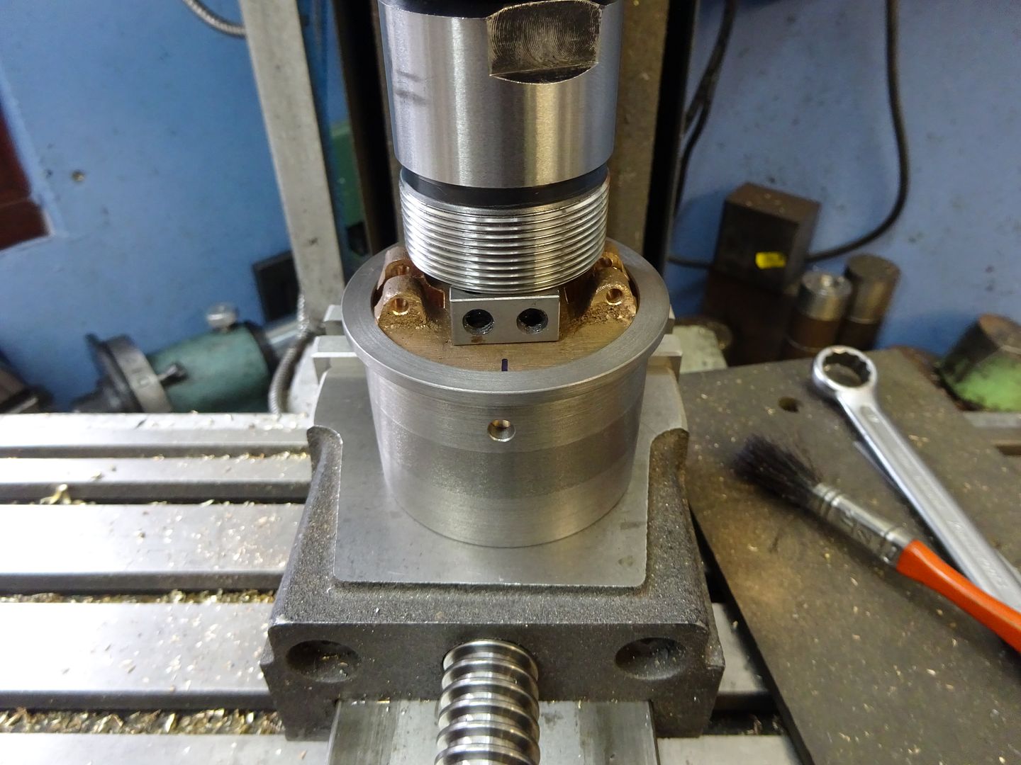
All that was left was to blend in the crown of the pully with teh assembled parts on a temporary shaft in the lathe.
J


