I have just received some additional information that Chelston Models also produced a larger version of this engine called the Jowitt Major but no other details about size etc.
The ModelChelston offered this with the base, cylinder and flywheels in cast iron the later of which were identical to Stuart 10 V/H flywheels and the extruded bearing material looks to have come from the same source. This engine is from the castings and made by Norman Peach who helped me with the drawings.
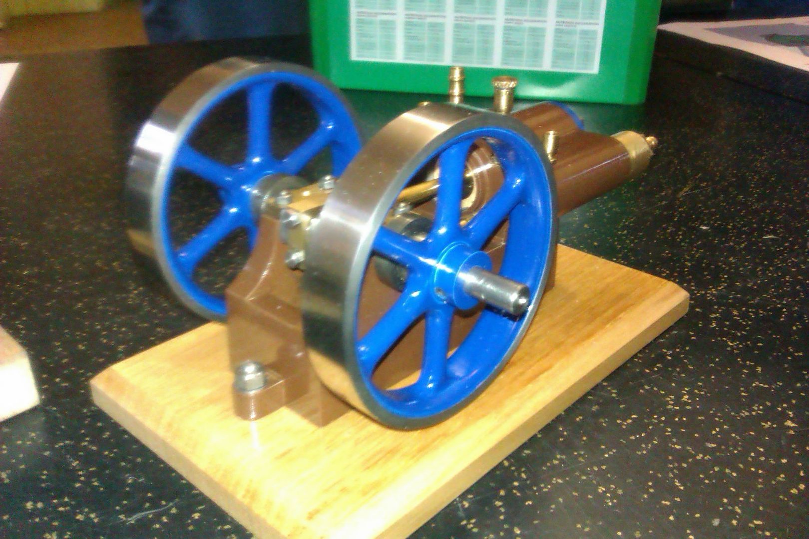
He also had a scratch built one with Aluminium base & cylinder and had used Stuart Flywheels & bearing material
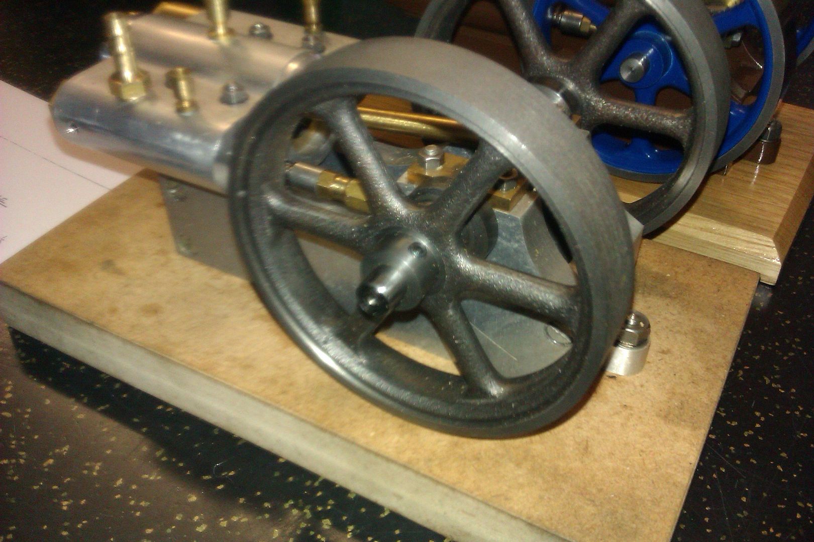
I decided to use a block of cast iron for the cylinder as I had some to hand though Aluminium should be upto the job if you like to keep your hands clean. The two flywheels came from Reeves and are their "Perseus" ones which clean up easily to the required 97mm of my larger version.
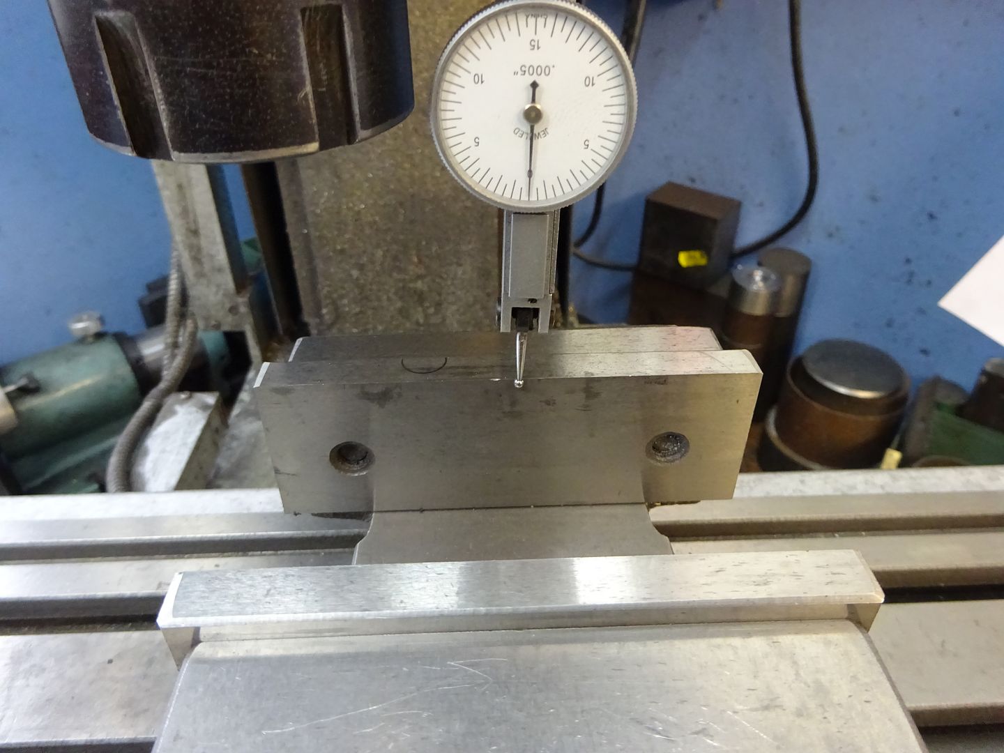
Frame SidesAs a lot of the set up will use fixed jaw of the vice as a reference its as well to check it is true to the Y-axis before starting.
The first job is to saw off two pieces of 2" x 0.5" aluminium a little over the required 140mm, set it in the vice on parallels and square up one end of each.
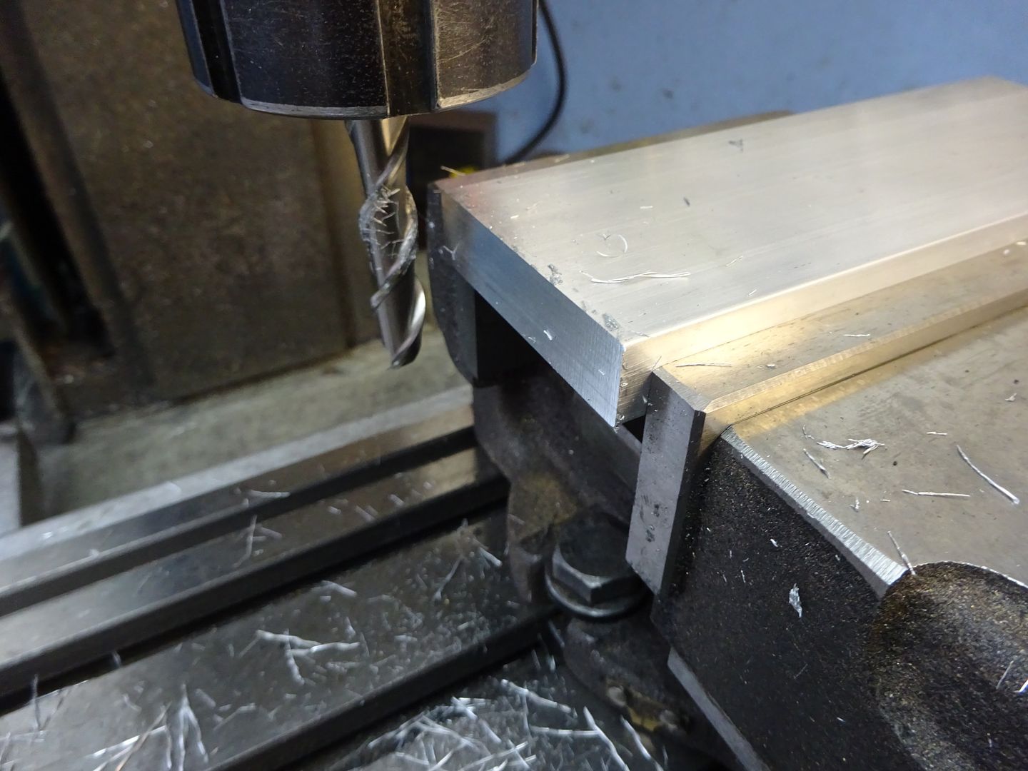
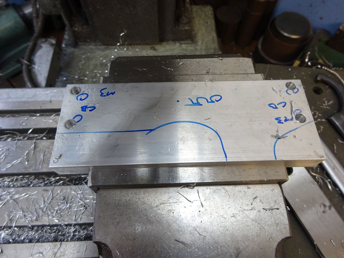
As the two sides are mirror images of each other it is easier to do most of the machining with the two pieces screwed together. After roughly sketching out where the holes & cuts go with a marker I set one side in the vice and used an edge finder to locate the bottom and previously squared end. The four M3 clearance holes can then be drilled and counterbored in one side, I set the holes 0.5mm higher than drawing to allow a skim to be taken off the bottom of teh extruded bar. If you don't have a counterbore then a 6mm milling cutter can be plunged in or an old drill reground to give an almost flat bottomed hole.
For the other side just drill two opposite holes clearance but tap the other two M3 which will allow the parts to be screwed together without the need for nuts sticking out the sides. You can see I have writen M3 against the ones to tap.
With the two plates stood back to back on a flat surface a couple of M3x12 cap head screws can be used to hold them together, then hold them in the vice bottom facing upwards and skim 0.5mm off to level the two surfaces and bring the screw holes to the drawing dimension of 5mm from the bottom. With that done grip them up the right way and mill the top down until you reach the required 50mm overall height. I used a flycutter for this but a couple of passes with a milling cutter will do.
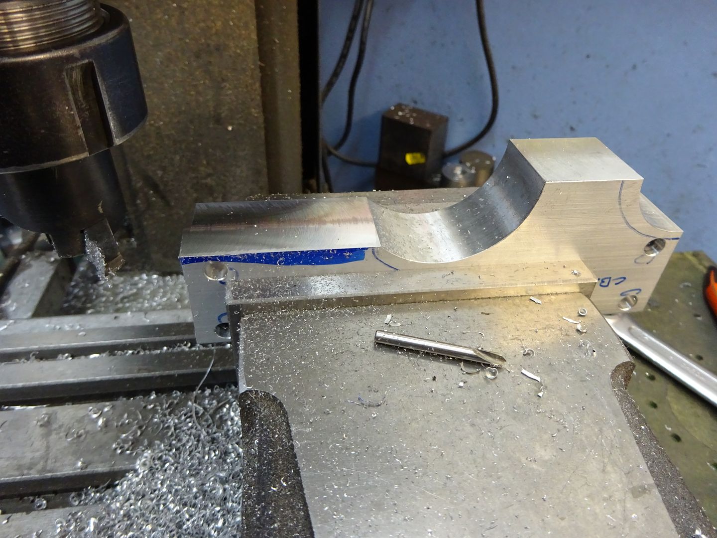
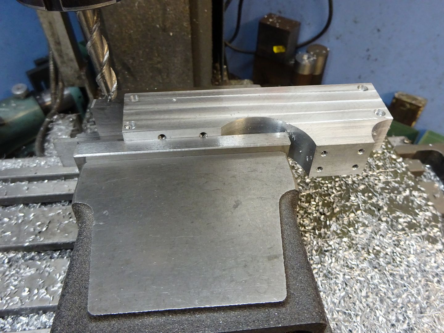
The curves that form the raised area for the crankshaft bearing can be formed with a boring head. Move the mill table so the spindle is 18mm away from the end of the work and then adjust the position of the cutter until it just kisses the end as you rock it back and forth by hand, this is an easy way to set the required 18mm radius.
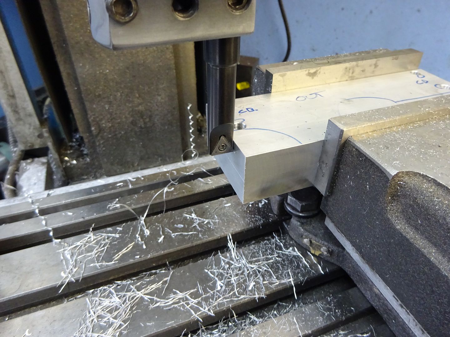
With the spindle 50mm from the vice jaw datum (bottom of frame) make a series of plunge cuts in 1mm steps until the spindle is 2mm in from the end of the work.
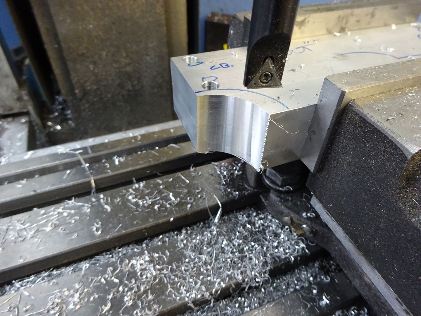
A similar method is used to set the radius on the other side to 24.5mm and the larger radius cut in the same manner.
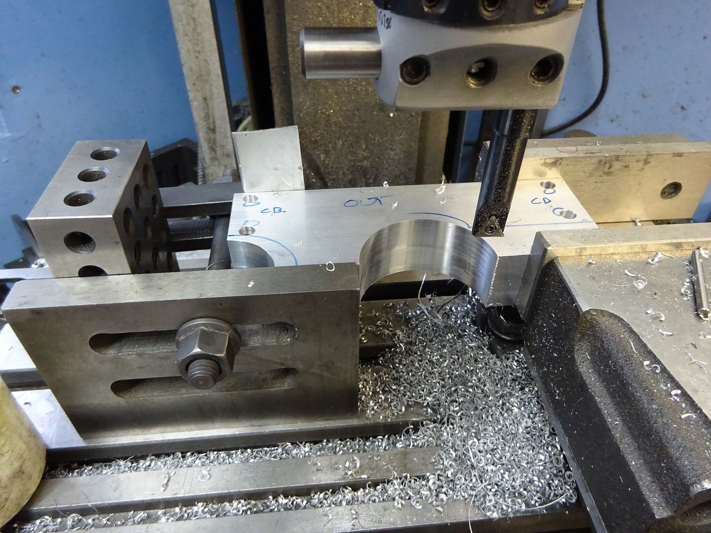
Scribe a guide line where the cylinder will sit 32mm up from the base and saw off the waste material leaving a mm or so to cean up on the mill. Save the two pieces that are cut off as they will do for the bearing caps later. Set up in the mill and machine until the required 32mm finished height is reached.
Locate the end of the frames and find the centre line of the pair using an edge finder and then drill and tap for the bearing caps and cylinder mounting studs. Note that the bearings are 5mm from the inside edge of the frames (ctr of pair) and the cylinder studs 6mm.
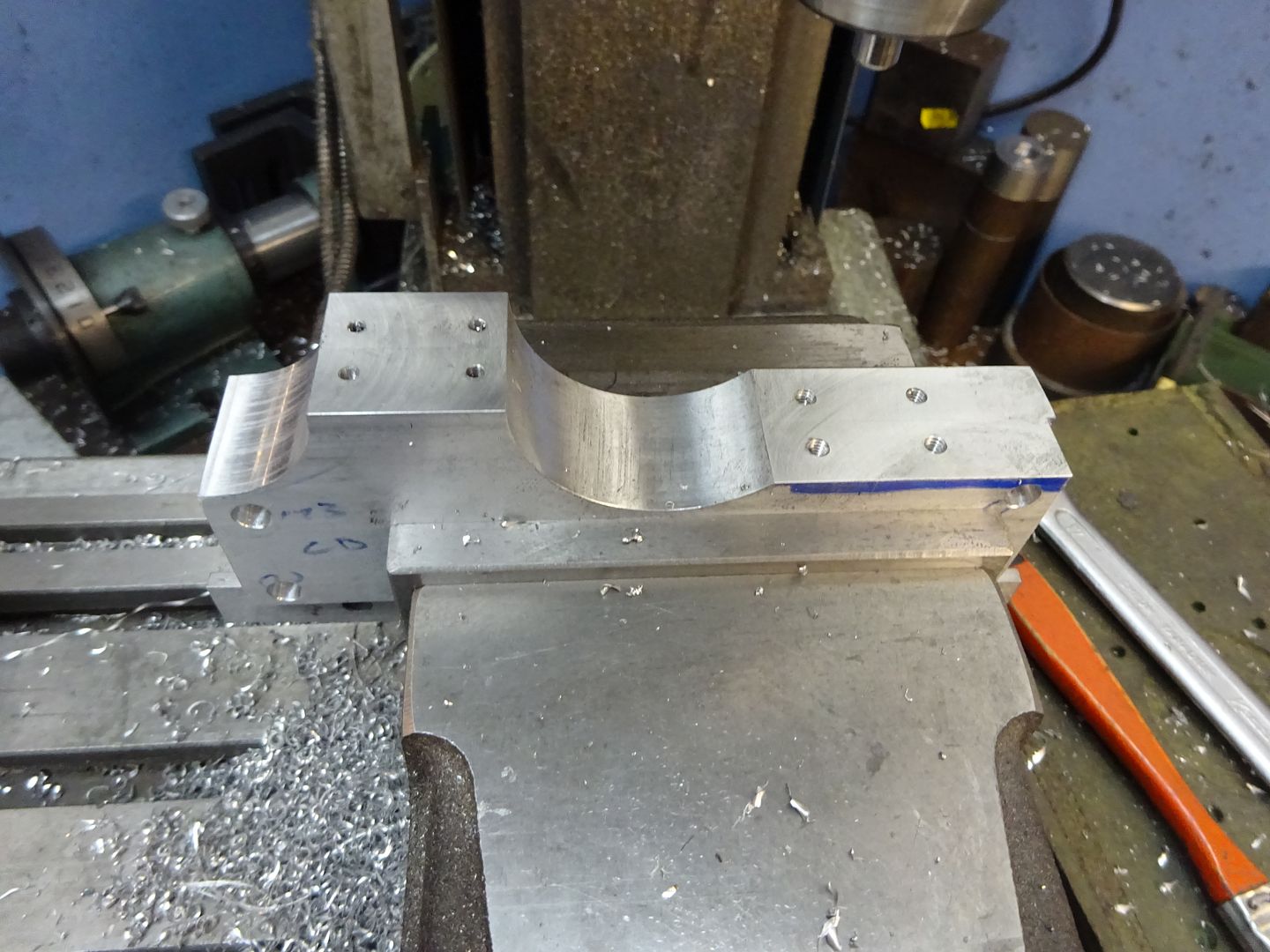
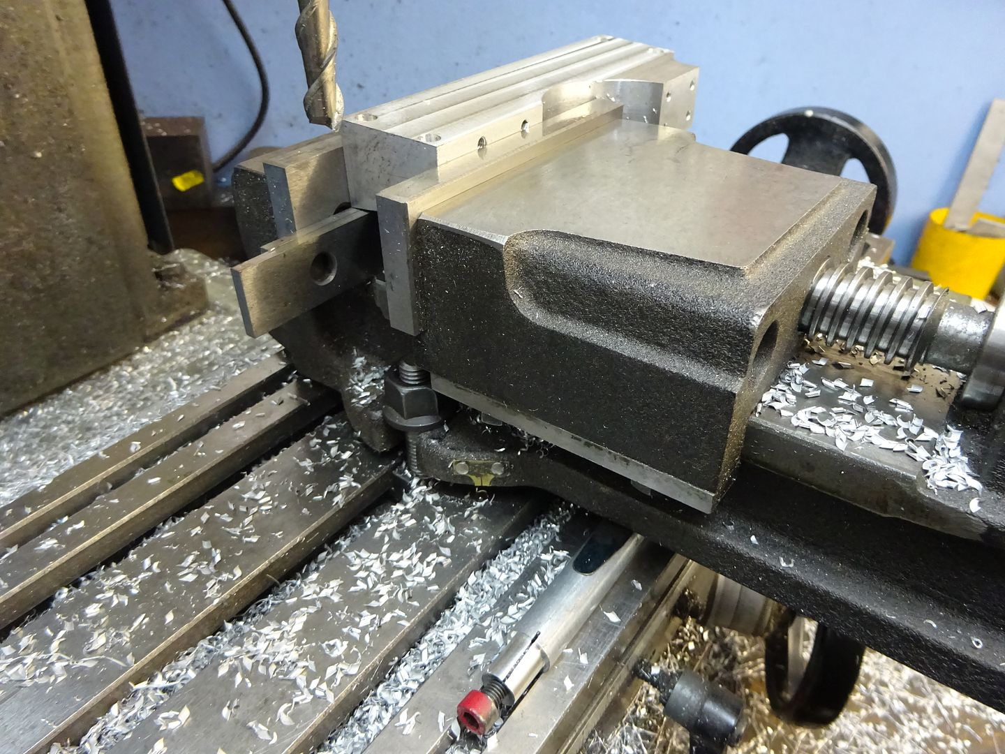
At the same setting the two vertical edges around the bearings can be reduced to the finished 10mm width, I used a 10mm dia cutter so it was simple to set the spindle 15mm from centre for the final cut. I took full 18mm depth cuts 0.5mm per pass using one of ARC's HSS cutters for Aluminium which romped through the metal.
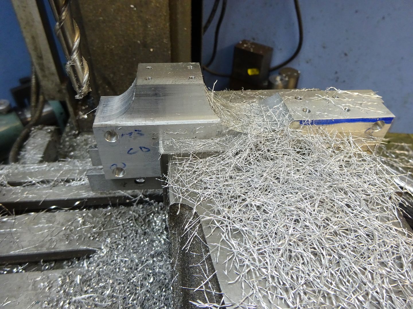
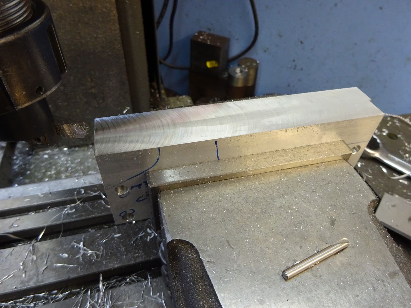
With the side frames upside down and held at 3.6deg the sloping ends can be cut and the overall length brought down to 140mm at the base.
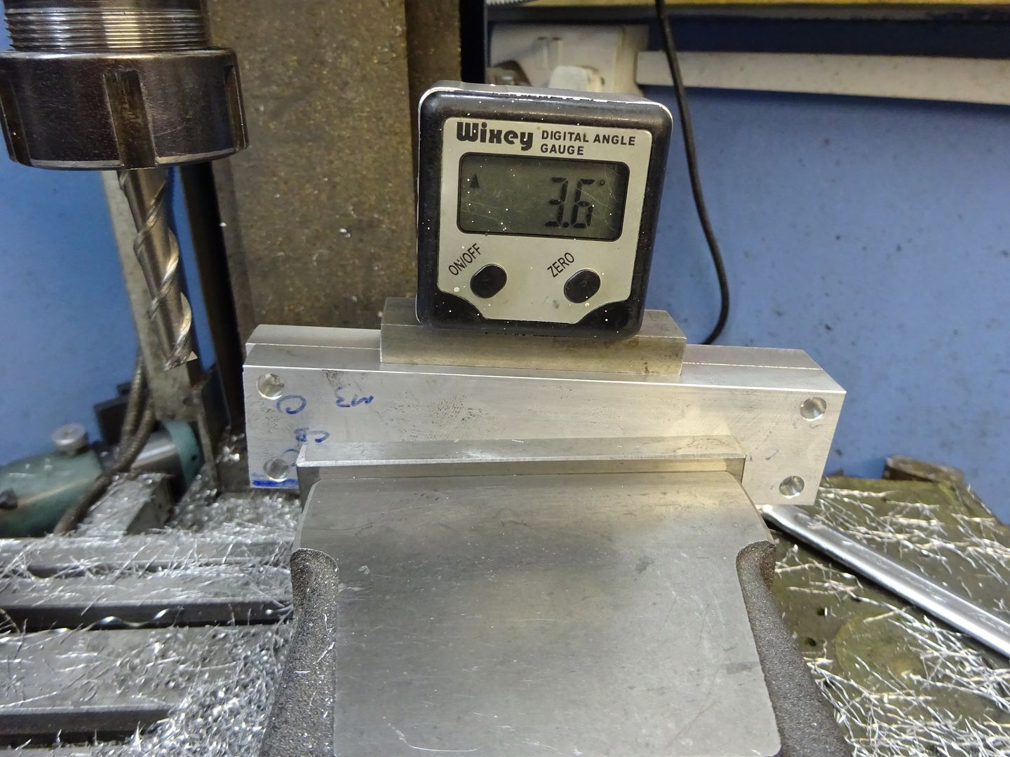
I don't have a tilting vice but its easy enough to pack up one end of a standard vice and then lightly bolt back down to the table to avoid distortion. The slope on the sides can then be milled to the same 3.6deg angle aiming to get a smooth transition where it meets the vertical face .
That is the side frames done, the pin hole to stop the bearings rotating will be drilled later
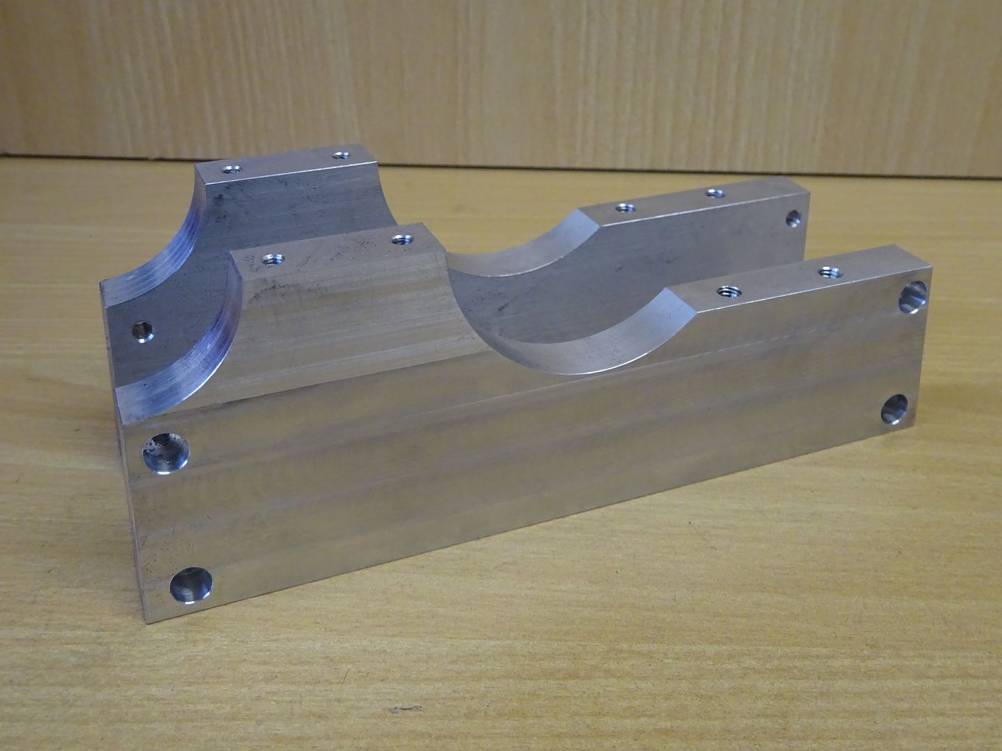
If you feel the sloping side may be a bit beyond what you are capable of then 10mm material could be used and the base done with straight edges. Next time I will cover the frame ends and feet.
J
Drawing attached


