Time to update this build with the little bit of progress seen over the past months ... before I forget what I did and how.
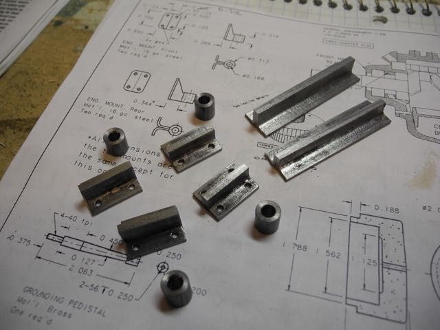
I'd left off at the connecting rods but decided to carry on with the engine mounts for a change. It was a chance to pay at small-scale fabrication. I found some square tubing of an appropriate size "in stock" that was split to create some right angles. Two angles were welded back-to-back to make the "webs" that bolt to the crankcase. These were then drilled for the crankcase studs and cut to length. Some solid round stock was drilled to clearance size and parted off to provide the vertical bits.
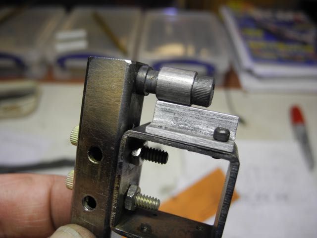
Then it was time for sorting out a way to hold these parts in alignment so they could be welded together. Yes, this was an opportunity to play with a TIG welder ... I wasn't comfortable with silver soldering/brazing these parts together given the loads they'd be under. Here is the fixture I came up with.
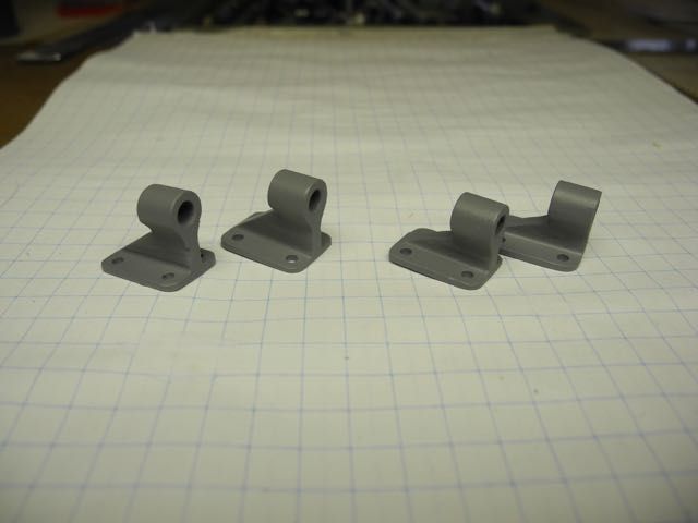
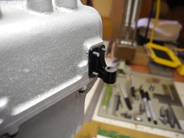
After a tidy-up, a bit of JB Weld and some primer I had some motor mounts.
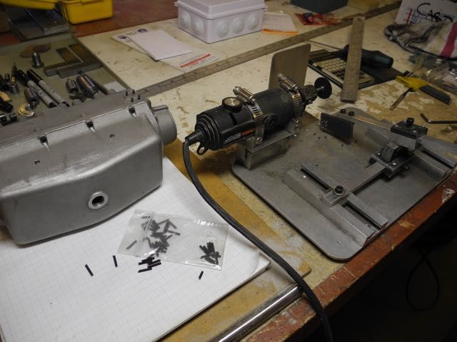
Fortunately I'd put together a gadget from Home Shop Machinist (?) some years back that made (relatively) quick work of cutting the 16 #2-56 studs to length. (This is one well used tool in a shop that does both aeromodeling and model engineering!)
... a bit of black paint and there you have it.
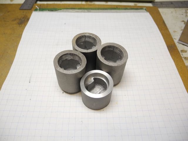
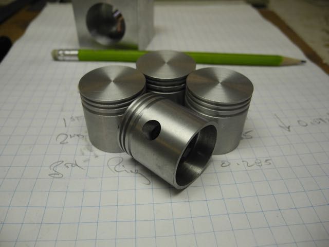
Then it was on to the pistons. These were the last of the castings and mighty fine ones too - no pin-holes! Here are three raw castings with one roughed to length and cleaned up inside.
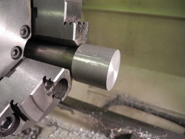
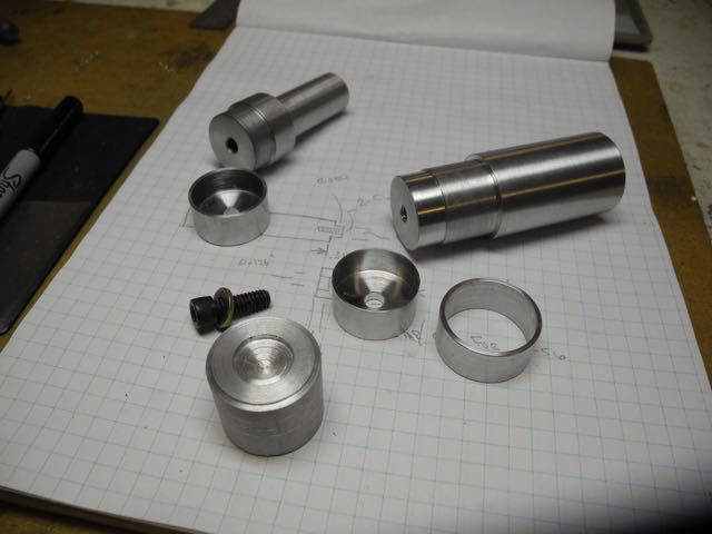
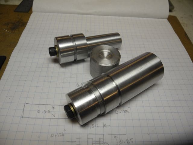
A mandrel was made up to hold the pistons via a heat-shrink fit. It was used to finish the pistons to length and near outside diameter.
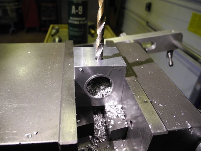
Another fixture was made up to hold the pistons while drill the wrist pin holes. It's just a block with a blind bore to match the pistons; cross-drilled to pin size.
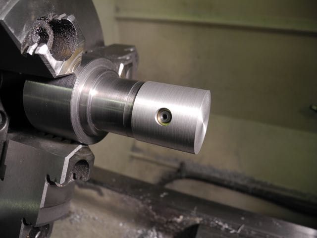
Now I could re-purpose a piston holding fixture made up ages ago. It only needed some bushes to size-up the "wrist pin" and a trim to match the piston inside diameter.
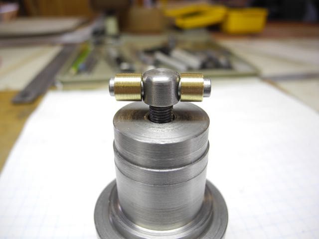
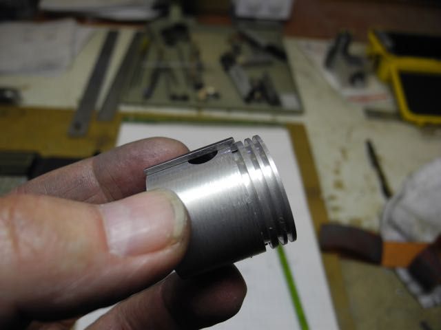
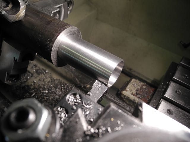
Here is a piston mounted on the fixture and cut to final diameter.
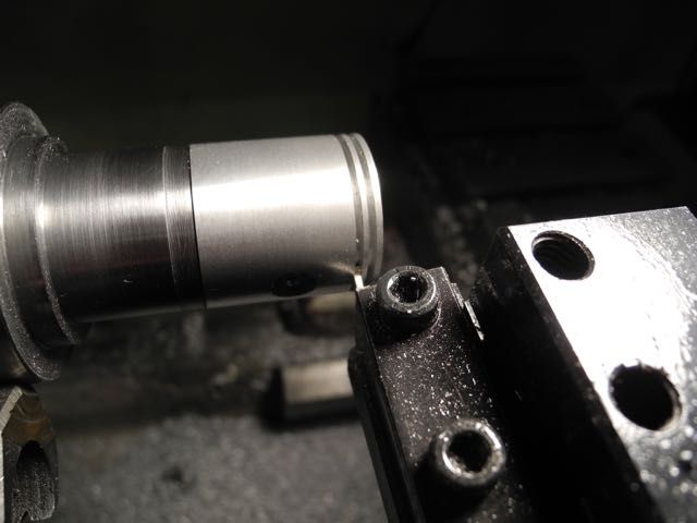
The piston ring grooves were cut with this setup. Plan to use two compression and one oil control ring.
The batch ...
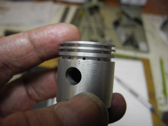
Model Engine Builder magazine included an article about oil control rings a while back. It illustrated a drilling jig for the piston oil control/drain holes that eliminated any chance for the drill bit to damage the grooves. Here is my iteration ...

... and the end result.
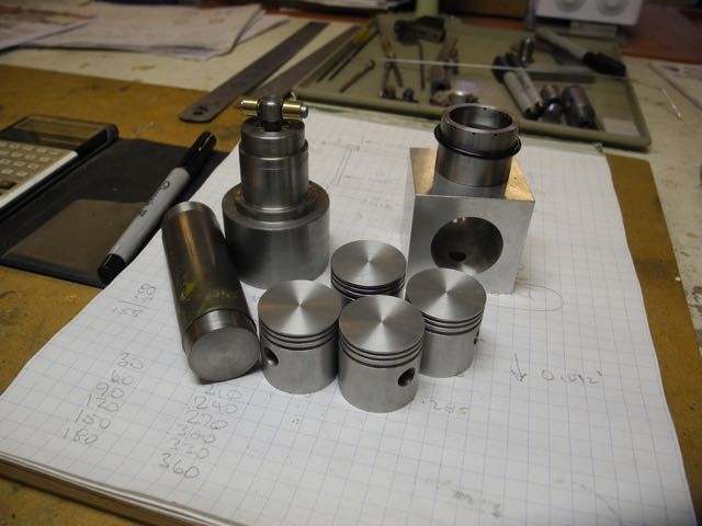
Here is a family photo including all the jigs/fixtures. It seems to takes more parts to make parts than there are parts themselves!
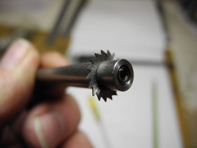
Next up were the piston rings - might as well stick to the theme! The oil control ring is going to be grooved and then that groove cut through in 12 places with a tiny saw. These blades are used for cutting electric motor commutators between segments. This one is 3/8" in diameter and needed an arbour made for it.
Next the fixtures were made to hold the rings while being burnished to width, trimmed to outside diameter, grooved (oil rings) and the gap cut. For this engine I'm going to use steel piston rings following (yet) another Model Engine Builder article. They are made to free diameter and the gap cut. No annealing required ...
The piston ring "tube" was then machined from some "stress-proof" 1134. It is bored to a calculated ID and turned to the free diameter (plus 10 thou for later finishing after parting off).
Well my friends, that is about it for this time. Now I just need to find a stretch of time to focus on parting off the ring blanks and carry-on finishing them.
Thanks for looking in ...
Charlie


