It has been ages since I last posted anything about the Cirrus. Too many of life's distractions getting in the way I guess. There has been some progress however small. In my world, any progress at all counts.
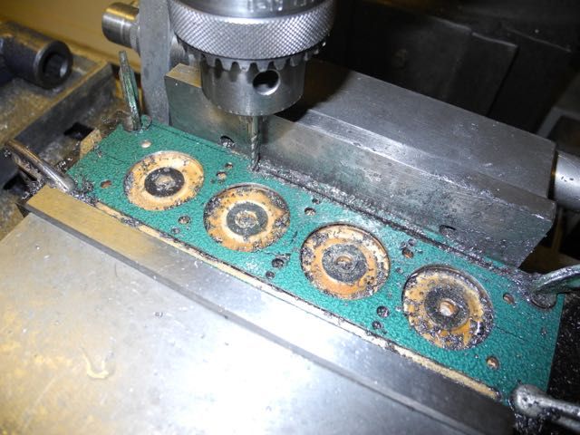
I had left off trying to decide what to tackle next and ended up doing the cylinder spigot plate. It is a thin plate that acts as a sort of cylinder spacing stabilizer if that makes any sense. The head sits directly on top of the cylinders. The cylinders each have a spigot long enough for an o-ring and then the plate. Anyway - I found a piece of steel of the right thickness and re-purposed it by cutting all the right holes and stripping the paint off.
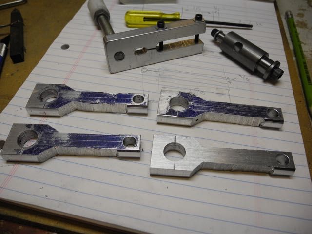
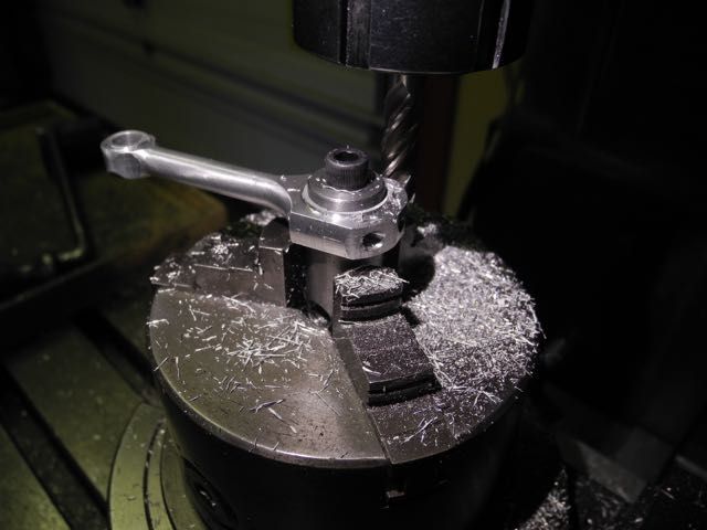
Next I tackled the connecting rods. All the blanks and the radius cutting tools needed got prepared in advance.
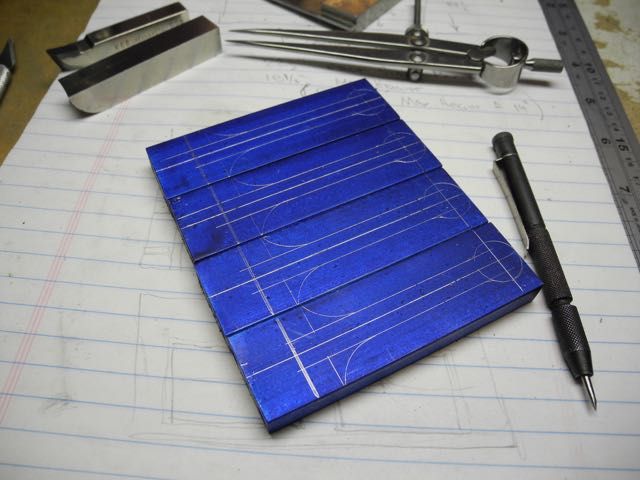
Then some centres were put in each end and the big-end cap screws were drilled to tapping and clearance sizes before cutting the caps off.
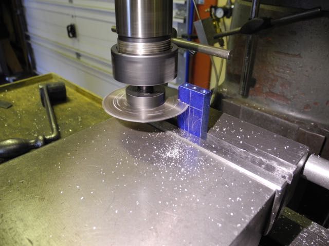
Once the outline was roughly cut back it was into the lathe to turn each end to size while mounted on centres.
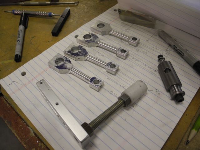
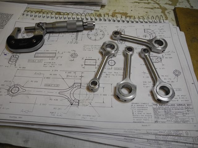
... might as well do all the rods together.
Then the middle section diameter was turned on all the rods.
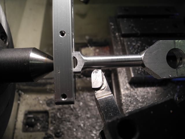
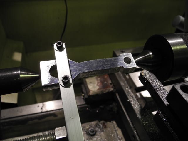
Another family shot; this time with the double-ended arbour used to turn the faces of each rod end.
Next the radii at each end were turned with 1/4" and 1/2" radius tools.
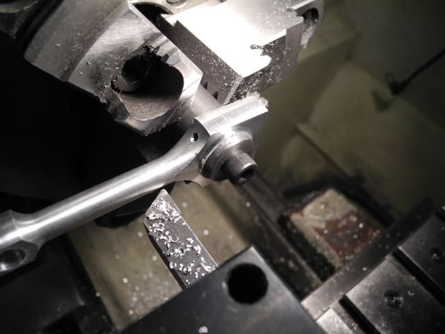
Here is a view of the rod end being trimmed back to reduce the face diameter.
Time for some rotary table work to round off the ends and make them pretty; used the same arbour.
Almost done ...
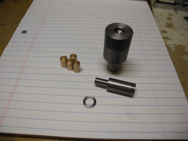
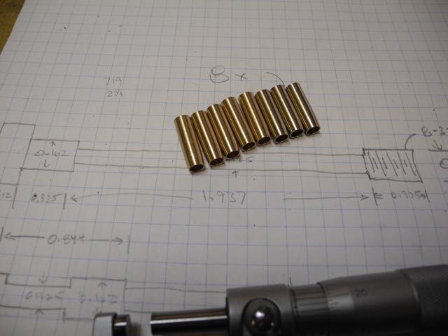
Here are the small end bushings (bronze) and the press tool and spacer used to ensure the bushing was inserted straight and with equal "stick-thru" on both sides.
Success ...
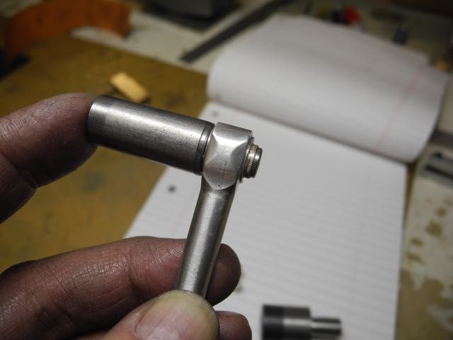
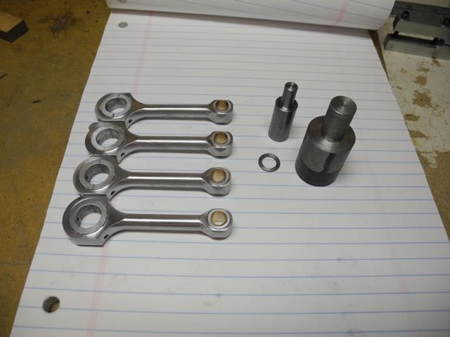
Now they are done.
Then it was on to the wrist (gudgeon) pins and their pads. The pads were made from "pop rivets". Thought I'd try after reading about using them somewhere. Don't know if I'd bother again; it may have taken the same time to turn up purpose-made ones.

While fiddling with little bits I figured I might as well get the (bronze) valve guides out of the way as well.
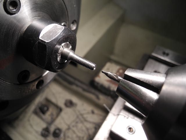
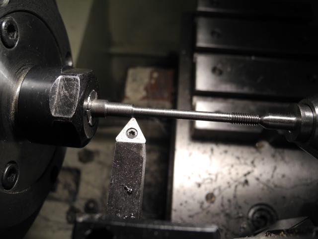
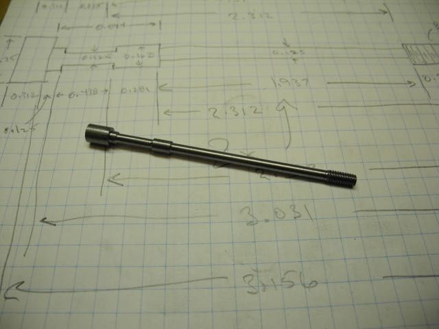
This is the beginning of the head bolts. There ten of them with two being longer and double-waisted. They are long relative to their diameter so I did the turning in stages and used a small centre throughout.
... about 1/2" at a time.
To get this ... this is a long bolt with an extra waisted section where the bolt goes through the siamese intake port.
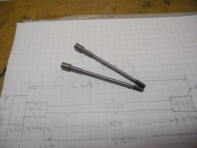
Here are a couple of the shorter ones.
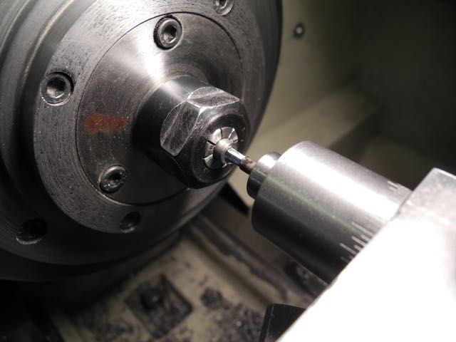
Once the end was trimmed to length and the socket head hole drilled to a couple thou over wrench size I could use my simple rotary broaching tool to cut the internal hex.
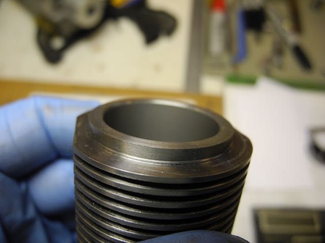
After all the new parts I went back to the cylinders and re-used a brass lapp from an earlier build to finish the cylinder bores. Didn't realize until after uploading the picture that the camera focused on the near side instead of the bore ... oh well, you get the idea. All cylinders ended up very close to each other (and print) and with a nice dull, smooth finish.
That's about it for this time.
Charlie


