Author Topic: 1/4 Scale Cirrus MkI  (Read 30430 times)

Offline Tjark

  • Full Member
  • ****
  • Posts: 353
  • Woldendorp, Netherlands
Re: 1/4 Scale Cirrus MkI
« Reply #45 on: January 13, 2016, 06:25:07 PM »
Charlie, a beautiful project.
My skills are far from this kind of work.
Will follow you progress.

   Tjark.

Offline cwelkie

  • Full Member
  • ****
  • Posts: 195
Re: 1/4 Scale Cirrus MkI
« Reply #46 on: February 14, 2016, 11:14:33 PM »
Well the wrist has healed well enough to get back in the shop, give it a bit of a tidy-up and get back to the cylinder head.  Even managed to get a couple more chuck stands thrown together to hold my faceplate and small 3-jaw properly.

Here is a picture of the spring loaded centre I put together for the rotary table.  I marked and centre punched the locations of the corner radius centres.  It was then easy to settle the spring loaded centre into the centre punch mark and clamp the head down for rounding over.


Once the head was lined up and clamped down there was nothing for it but to start cutting the grooves.


I cut the fins all four sides without moving the head - figured it was best way to ensure the beginning and end of the groove ended up in the same place.  I then mounted the head with the exhaust side down to cut all the grooves I could reach including finishing them to the same depth on the ends.


Then the head was flipped over and the last two grooves cut in ...


After a bit of tidying it looks like a keeper ... as mentioned before, I reckon this piece now holds the record for the highest number of machine operations and setups in a single part.


I managed to get the crankshaft and cylinder stock cut to length as well so I guess I'll have to flip a coin to see which bit is next.
As always - hope this is of some interest.
Cheers
Charlie


Offline zeeprogrammer

  • Full Member
  • *****
  • Posts: 6811
  • West Chester, PA, USA
Re: 1/4 Scale Cirrus MkI
« Reply #47 on: February 14, 2016, 11:28:45 PM »
Nice looking parts!!

I didn't know about your wrist. Hope all is well now.
Carl (aka Zee) Will sometimes respond to 'hey' but never 'hey you'.
"To work. To work."
Zee-Another Thread Trasher.

Offline Dave Otto

  • Full Member
  • *****
  • Posts: 4712
  • Boise, Idaho USA
    • Photo Bucket
Re: 1/4 Scale Cirrus MkI
« Reply #48 on: February 15, 2016, 01:07:45 AM »
Impressive piece of work Charlie!

You have got be be pretty darn happy with that.

Dave

Offline cwelkie

  • Full Member
  • ****
  • Posts: 195
Re: 1/4 Scale Cirrus MkI
« Reply #49 on: April 11, 2016, 12:04:42 AM »
Gosh - it's been almost a month since any update on this thread ... it must be motorcycle season  ;D
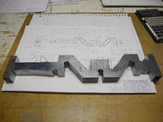
I've made some progress on the crankshaft though.  It started with a piece of annealed 4140 that was available in flat stock of the right dimensions.  That saved some work compared to starting with full round 1144.  So, after a layout session and some time for the subconscious to double check for any errors it was time to drill some holes and cut off some extra bits.


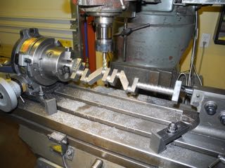
I then setup the blank on the mill using a vertically mounted rotary table and tailstock.  I wanted to try the technique of milling off the square corners to avoid as much interrupted cutting as possible.  It worked fine but I'm not sure the bother of setting it all up was worth it.  I suppose one would have to do two cranks, one each way, to really know.  In any event, it made setting the journal spacing easy.


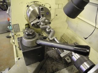
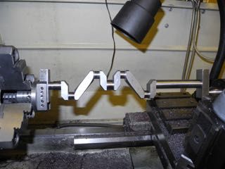
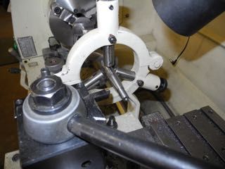
You might just make out a centre fixture I'd made for use on the driven end of the crank.  It was from an Model Engine Builder article and I am happy with how secure it held the end of the crank and made changing centre easy and secure.  Here the crankshaft to be is in the lathe having the journals cut and "webs" cleaned up.


The journals polished up nicely with some emery and then wet/dry.  Even got them all within 1/4 thou of each other (near as I can measure anyway.


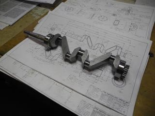
Once all the between centres work was done on the journals it was time for that irreversible step of "cutting off the ears".  I did the prop end first so I could still drive the crank using the fixture.  Supported the end with a fixed steady to cut the threads and taper.  Then the "back end" was cut off, cleaned up and drilled for the cam drive gear screw and shoulder.


After all was said and done, the bearings and the gear slipped on with just the right amount of resistance.  Pleased about that.  (Reminds me of a flying instructor from years ago ... "trust your instruments", he'd say)


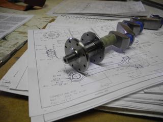
While fiddling with crankshaft bits, might as well do the prop hub and washer.


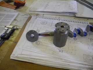
... and they fit too!


Now that I've caught up with these photos, next up will be the cylinders.  I've roughed out a mandrel to hold them while turning the external features.  I'll finish sizing the mandrel once I bore all the blanks to size (slitting it seemed to have relieved a little bit of stress in the material).  Here's hoping I can get all four cylinders to the same size; within reasonable limits of course.  ;)

Until next time.
Charlie


Offline gbritnell

  • Full Member
  • ****
  • Posts: 2477
Re: 1/4 Scale Cirrus MkI
« Reply #50 on: April 11, 2016, 12:11:16 AM »
Really nice work Charlie!
gbritnell
Talent unshared is talent wasted.

Offline Tennessee Whiskey

  • Full Member
  • *****
  • Posts: 3781
  • Springfield, Tennessee. USA
Re: 1/4 Scale Cirrus MkI
« Reply #51 on: April 11, 2016, 12:22:38 AM »
Now that is one sweet crankshaft and a super job of achieving it  :ThumbsUp: :ThumbsUp: :cheers:.

Cletus

Offline b.lindsey

  • Global Moderator
  • Full Member
  • *****
  • Posts: 13860
  • Dallas, NC, USA
    • Workbench-Miniatures
Re: 1/4 Scale Cirrus MkI
« Reply #52 on: April 11, 2016, 12:37:10 AM »
Both the heads and the crankshaft are beautiful examples of machining Charlie. Well done!!

Bill

Offline zeeprogrammer

  • Full Member
  • *****
  • Posts: 6811
  • West Chester, PA, USA
Re: 1/4 Scale Cirrus MkI
« Reply #53 on: April 11, 2016, 12:49:54 AM »
 :o

Just don't know what to say. Wow...what a part.
Carl (aka Zee) Will sometimes respond to 'hey' but never 'hey you'.
"To work. To work."
Zee-Another Thread Trasher.

Offline Dave Otto

  • Full Member
  • *****
  • Posts: 4712
  • Boise, Idaho USA
    • Photo Bucket
Re: 1/4 Scale Cirrus MkI
« Reply #54 on: April 11, 2016, 12:53:42 AM »
Nicely done Charlie!

The crankshaft and prop hub both look great.

Dave

Offline petertha

  • Full Member
  • ****
  • Posts: 785
Re: 1/4 Scale Cirrus MkI
« Reply #55 on: April 11, 2016, 07:51:32 PM »
Very nice Charlie.
When you say 'annealed 4140', do you mean it was purchased that way, or you did some baking on you own?
Anything special about cutting tool type/geometry or it machined pretty well with conventional tooling?

Offline Roger B

  • Global Moderator
  • Full Member
  • *****
  • Posts: 6172
  • Switzerland
Re: 1/4 Scale Cirrus MkI
« Reply #56 on: April 11, 2016, 08:07:17 PM »
That's another very nice bit of fabrication  :praise2:  :praise2:
Best regards

Roger

Offline cwelkie

  • Full Member
  • ****
  • Posts: 195
Re: 1/4 Scale Cirrus MkI
« Reply #57 on: April 12, 2016, 01:09:19 AM »
Thanks all for the encouragement and providing the incentive to keep moving forward ... I get to feeling guilty if I haven't put anything up for awhile.

Peter - the 4140 was purchased in the annealed state.  Was rather surprised to see it available in the rectangular section.  It cut beautifully on the powered hacksaw and drilled easily.  I admit to being challenged on the surface finish though.  I never did get the surface finish I'd hoped for or expected on the webs.  Tried carbide and HHS; different speeds and feeds.  Had the part made before I found the sweet-spot.

For the journals I got the best result with a bi-furcated grind on a HHS cutoff blade.  (added maybe 5 degrees back rake)  The finish wasn't bearing-ready but that was sorted easily and quickly with a couple grades of emery and then a polish with some 600 wet/dry supported by the back of some worn energy strips.  I was surprised at how quickly the journals finished - good thing I left a good 2/3 thou for finish work.

Will I use it again ... only to use up the extra material brought in (always make sure I have "re-do stock"!).  It's back to stress proof for me.  If I try something new next time it will be to anneal some cold rolled rectangular cross section in the shop.  (Managed to re-purpose a ceramic kiln a few years back ... )

Long winded response - hope it's of some use.
Cheers
Charlie

Offline petertha

  • Full Member
  • ****
  • Posts: 785
Re: 1/4 Scale Cirrus MkI
« Reply #58 on: April 12, 2016, 08:01:13 PM »
Thanks for useful comments. Exactly what I wanted to know. Just about to try stress proof myself for the first time, so good to know you came to this conclusion.

Offline cwelkie

  • Full Member
  • ****
  • Posts: 195
Re: 1/4 Scale Cirrus MkI
« Reply #59 on: May 08, 2016, 01:49:43 AM »
Well ... I'm still at it; albeit very slowly.  This time I'll share the journey in making the cylinders.  They are of 12L14 (Leaded steel) only because I've had good luck using it for cylinders before and I very much like the relatively stress-free way one can cut (thin) fins in it.

I started with four "blanks" that were turned to length plus a bit and then bored/honed to within a thou of target bore diameter.  I plan to lap them to final dimension after I sort out if I'm going to colour them (black) or not ... but that's another story.


The arbor was turned to a few thou oversize, then slit (free-hand on the bandsaw).  The "wedge screw" is just a socket head cap screw with a 60 degree taper turn on the bottom of the head to match a taper cut with a large centre drill.


Once I was ready to work on the cylinders I put the arbor into the lathe, tightened a thick washer on the end to hold the split sections in place and finish turned the OD.  Then it was down to cutting away the bits that didn't belong and on to cutting the fins.  I ground a HSS blank into a 0.050" wide tool deep enough to reach in 0.300" or so.


Then the cylinders could be turned around, this time spaced away from the arbor to provide an easy reference for cutting the overall length and upper spigot depth.  Also used the same setup for each cylinder to cut the inside, upper chamfer and the angle on the lower fins.


... and then there were four cylinders.


To fit the crankcase spacing, flats are cut on the cylinders to provide the required clearance so a walk over to the mill was next.


With great satisfaction, they fit the crankcase with the same subtle gap.


At this point I just couldn't resist digging out the head for a look-see ...


So far so good - everything seems to be lining up nicely.  Guess I need to go on the prowl for some 18 gauge sheet steel for the cylinder spigot/spacing plate ... or find that length of 3/8" 2024 for the connecting rods ... or decide if I should blacken the cylinders or not ...

Thanks for looking in.
Charlie


SimplePortal 2.3.5 © 2008-2012, SimplePortal