Author Topic: 1/4 Scale Cirrus MkI  (Read 30294 times)

Offline zeeprogrammer

  • Full Member
  • *****
  • Posts: 6811
  • West Chester, PA, USA
Re: 1/4 Scale Cirrus MkI
« Reply #30 on: January 09, 2016, 04:05:39 PM »
Wow. That's some nice stuff there.  :ThumbsUp:
Carl (aka Zee) Will sometimes respond to 'hey' but never 'hey you'.
"To work. To work."
Zee-Another Thread Trasher.

Online Jo

  • Administrator
  • Full Member
  • *****
  • Posts: 15305
  • Hampshire, england.
Re: 1/4 Scale Cirrus MkI
« Reply #31 on: January 09, 2016, 04:06:46 PM »
Now you are worrying me  :paranoia: this is one of my engines for my future retirement when I hope might have a better idea what I am doing but  :o

This is all good stuff Charlie, I can tell I am going to have to work up to this engine  ;)

Jo
Enjoyment is more important than achievement.

Offline petertha

  • Full Member
  • ****
  • Posts: 784
Re: 1/4 Scale Cirrus MkI
« Reply #32 on: January 09, 2016, 04:56:00 PM »
Very nice!

Can you elaborate on your rockers & tappets & overall hardening strategy for valve drive train. Tool steel? Fully hardened vs. just on the ends where it needs it? Are you alternating hardened to non-hardened mating surfaces to confine wear to certain parts? I'm just making up a jig plate to mill the overall profile, but also serve double duty to profile the tricky little rocker/valve sliding face radii. I have no idea if this is going to work. Would love to hear how you approached this aspect on your rockers.

Re the 2-jet carb design, do you mean like a main & idle fuel circuit, or 2 main fuel jets for better flow/atomization or something?

Offline petertha

  • Full Member
  • ****
  • Posts: 784
Re: 1/4 Scale Cirrus MkI
« Reply #33 on: January 09, 2016, 05:06:44 PM »
You mentioned building this angle plate yourself. I'm very interested to know more details. Is it from your own design or casting kit or? Its such a nice low profile design. The commercial ones I've seen appear much larger, expensive & I get the impression more for grinding setups vs. milling operations. Sorry for all the questions, feel free to post separately in Tools section or wherever so I don't off-topic your Cirrus post.

Offline Don1966

  • Full Member
  • *****
  • Posts: 6818
  • Columbia, MS
Re: 1/4 Scale Cirrus MkI
« Reply #34 on: January 09, 2016, 05:40:43 PM »
Nice progress Charlie and I would like to see more operation photo of how you go about making these gorgeous parts. You made your own  gears and do you have photo making them? I am also curious of you angle plate.

Don

Offline b.lindsey

  • Global Moderator
  • Full Member
  • *****
  • Posts: 13860
  • Dallas, NC, USA
    • Workbench-Miniatures
Re: 1/4 Scale Cirrus MkI
« Reply #35 on: January 09, 2016, 06:21:41 PM »
Most impressive work Charlie....even all the little bits!! Looking forward to more now in real time :)

Bill

Offline smfr

  • Full Member
  • ****
  • Posts: 1203
  • San Francisco Bay Area, California
Re: 1/4 Scale Cirrus MkI
« Reply #36 on: January 09, 2016, 06:49:34 PM »
Those are some amazing-looking parts, Charlie!

Simon

Offline cwelkie

  • Full Member
  • ****
  • Posts: 195
Re: 1/4 Scale Cirrus MkI
« Reply #37 on: January 09, 2016, 07:01:17 PM »
Thanks everyone for your kind comments.
Jo - you won't have any trouble with this build given what I've seen you take on with great success.  All the bits are just little projects by themselves ... eventually there are enough to assemble an engine.

Peter - no worries about all the questions; that's why we share this stuff anyway isn't it?  I'll try the easy ones first.

Don - sorry no photos of cutting the gears.  Best I can offer are some of the arbor and hobs used to cut them.  Let me know if that is of interest.  The gear blanks were on an arbor in the vertically mounted rotary table.  The hob was on another arbor in the mill spindle.  Not terribly difficult just time consuming.  Very grateful for power feed and having converted the rotary table to receive a stepper motor drive.

The carb design is a two-jet arrangement, that is a mixture control for both idle and high speed.  To a large degree that's what attracted me to it - and the fact that it was well thought out from a "buildability" perspective.

I am only planning to harden contact areas on the rockers and the tappets.  The tappets are made of drill rod (tool steel) so that's easy.  The rockers are of cold-rolled so I'll be using Cherry Red case hardening compound for them.  I used this material when I hardened the saw I showed earlier and it worked very well ... be sure to have plenty of ventilation though.  I don't anticipate a need to harden much else in the valve train so I guess yes, I'll be hardening one side of a contact pair and leaving the other "soft".

The adjustable angle plate was actually done in anticipation of this build.  It has however seen a great deal of use for many other "little things".  Between the plate and a digital angle gauge I'm feeling right spoiled.  I purchased castings for the angle plate from College Engineering in the UK.  I also brought over one of their Keats Angle Plates to spread the per unit postage  ;D  The castings were of very good quality.  The Keats hasn't been used as more than an extra right angle plate yet but it is nice have around just for that.  Harold Hall (from the UK) did an article in Model Engineering Workshop on both - there may be more information on his website. Let me know if you'd like some pictures of it/them.

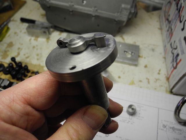
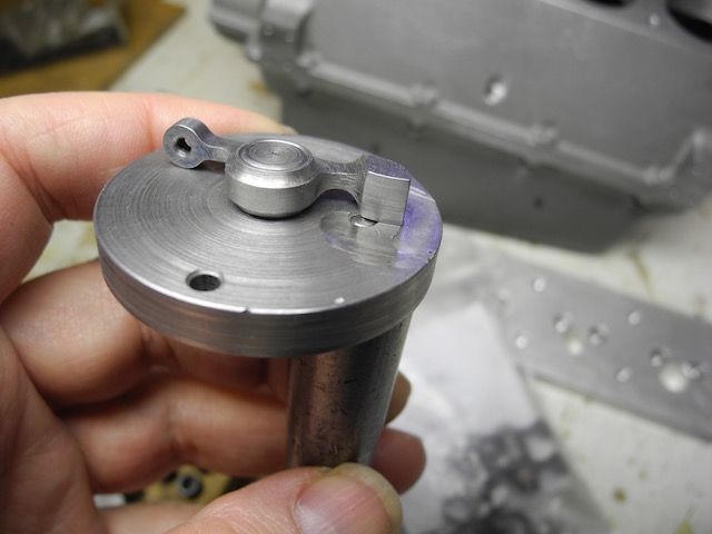
Now the tricky bits, the rocker arms - and more "feeling bad" for not taking pictures of the setups ... but I'll try to describe them best I can.
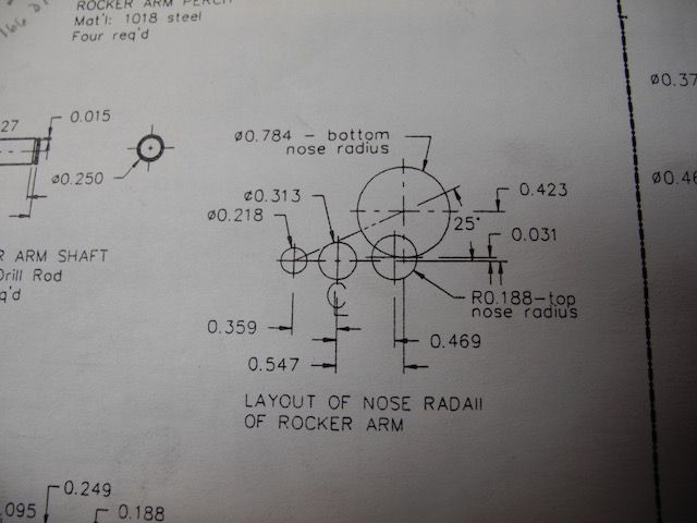
First off, the drawing detailed the radii centres for the nose and other important features.  The 0.313 hole near centre is the pivot hole.


Each disc of material that was going to end up being a rocker arm was sliced off the stock, faced and dimensioned to thickness.  The centre pivot hole was also drilled/reamed while in the lathe.  They could then be put on the rotary table to have an index pin hole drilled and a clearance hole drilled for a machine screw hold-down.

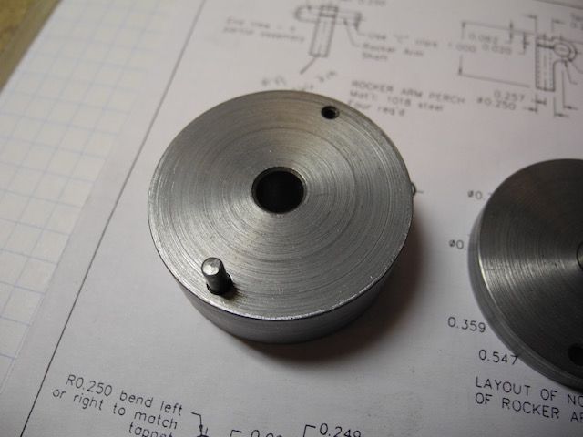
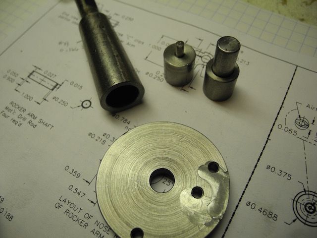
A lathe holding fixture was then made up with a matching centre pivot hole, index pin hole and a thread hole for the machine screw anchor.  Here is the lathe fixture:


Now a radius cutter could be used to cut the groove in both sides of all the rocker blanks.  After this each blank had a shallow curved depression all the way around the blank on both sides.

Some where in here I made a index plate for use on the rotary table.  This plate has a centre pivot hole of the same dimension as the rocker arms, an index pin hole to match the one in the "lathe fixture" and two more to pickup the nose radii centres.  Like this:
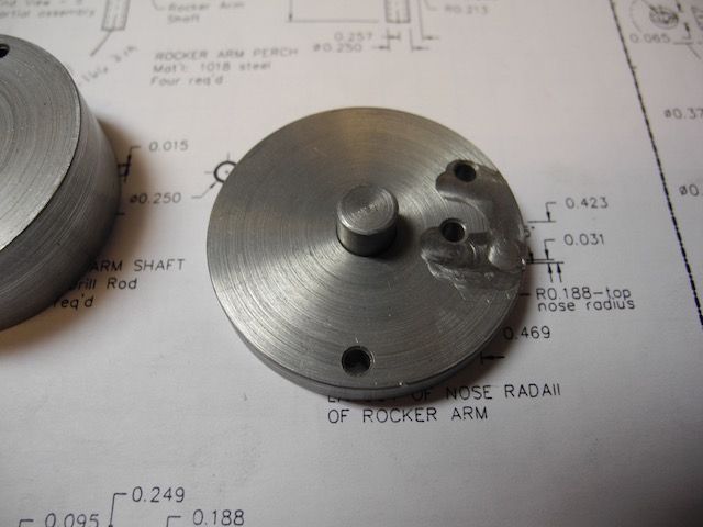


Here is another picture of the fixture plate on top of the "lathe fixture" with both index pins in place:
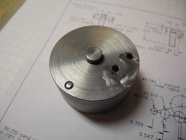


With the rotary table centred under the spindle I could now place the rocker arms on the fixture and on each of the critical centre points in turn to cut the arcs.  There was some messing around with moving clamps for every operation and some planning ahead required to be sure there was something to clamp on.  In the end I think it worked out pretty well - even the "spare" made it through without mishap.


All the best everyone!
Keep the questions coming - glad to be of any small assistance.
Charlie

Offline 10KPete

  • Full Member
  • ****
  • Posts: 1606
  • Nordland, WA, USA
Re: 1/4 Scale Cirrus MkI
« Reply #38 on: January 09, 2016, 07:12:11 PM »
I would be very interested in seeing pics of your angle plate as I also have a low overhead mill and frequently need to do
angle cuts that can't be done in the vise or flat. Cutting a piece of wood for each job is problematic!

Pete
Craftsman, Tinkerer, Curious Person.
Retired, finally!
SB 10K lathe, Benchmaster mill. And stuff.

Offline cwelkie

  • Full Member
  • ****
  • Posts: 195
Re: 1/4 Scale Cirrus MkI
« Reply #39 on: January 09, 2016, 10:08:34 PM »
So here you go (Pete, Don and Co) ... more about the adjustable/tilt angle plate I used.

As mentioned, the castings came from College Engineering.  They have two sizes - the one I have is the larger of the two.  Here is a link to the web page that lists their angle plate castings:

http://www.collegeengineering.co.uk/AnglePlates.htm

Harold Hall does have a page on his website about this angle plate as well:

http://www.homews.co.uk/page326.html

I'm sorry I couldn't level it for a better idea of its height in that plane ... only so much I can do with one hand (clamping bolts too tight).  These pictures might help.  It is sitting on a 9"x42" mill table (Bridgeport clone).


One thing I plan to do to mine is drill and tap some holes along adjacent edges to act as a fence in both directions.  This will help not only in the setup of multiple parts but also in the setup of a single part that needs to held to a reference.  (It would also help to keep things from sliding off   :LittleDevil: )  I've also been hemming and hawing about adding T-slots as Mr. Hall did but have so far been satisfied with the slots.  (I did machine the underside around the slots so that I can T-nuts anyway - they just aren't captured.

Charlie


Offline 10KPete

  • Full Member
  • ****
  • Posts: 1606
  • Nordland, WA, USA
Re: 1/4 Scale Cirrus MkI
« Reply #40 on: January 09, 2016, 11:10:04 PM »
Thanks for the pics Charlie! I kinda figured it was a simple thing but one never knows, do one?

That's a neat engine you're building and the workmanship is great. I love the details.

Pete
Craftsman, Tinkerer, Curious Person.
Retired, finally!
SB 10K lathe, Benchmaster mill. And stuff.

Offline Don1966

  • Full Member
  • *****
  • Posts: 6818
  • Columbia, MS
Re: 1/4 Scale Cirrus MkI
« Reply #41 on: January 09, 2016, 11:32:51 PM »
Charlie thanks for the feedback and I do like the angle plate........ :ThumbsUp:

Don

Offline Graham Meek

  • Full Member
  • ****
  • Posts: 310
Re: 1/4 Scale Cirrus MkI
« Reply #42 on: January 12, 2016, 03:20:21 PM »
Hi Charlie,

I have just been reading this post for the first time. I like the work you are doing and I was really taken by the vernier adjustment on the camshaft gear as well as the lovely sculpted rockers. I shall make a point of looking in on this post more often

My best regards
Gray,

Offline cwelkie

  • Full Member
  • ****
  • Posts: 195
Re: 1/4 Scale Cirrus MkI
« Reply #43 on: January 13, 2016, 03:45:23 PM »
Thanks Graham for the kind comments.  I too was quite pleased with how those pieces turned out.
I've recently spent a few hours studying your facing/boring head design and will need some serious determination not to be distracted by it ... at least until I can get the cylinder head finished.
Cheers
Charlie

Offline Graham Meek

  • Full Member
  • ****
  • Posts: 310
Re: 1/4 Scale Cirrus MkI
« Reply #44 on: January 13, 2016, 04:57:28 PM »
Hi Charlie,

I see the mention to my boring head earlier on in your post. If it is any help I made one for a friend just before Christmas and it took me about 30 hours in total.

My best regards
Gray,


SimplePortal 2.3.5 © 2008-2012, SimplePortal