Thanks everyone for your kind comments.
Jo - you won't have any trouble with this build given what I've seen you take on with great success. All the bits are just little projects by themselves ... eventually there are enough to assemble an engine.
Peter - no worries about all the questions; that's why we share this stuff anyway isn't it? I'll try the easy ones first.
Don - sorry no photos of cutting the gears. Best I can offer are some of the arbor and hobs used to cut them. Let me know if that is of interest. The gear blanks were on an arbor in the vertically mounted rotary table. The hob was on another arbor in the mill spindle. Not terribly difficult just time consuming. Very grateful for power feed and having converted the rotary table to receive a stepper motor drive.
The carb design is a two-jet arrangement, that is a mixture control for both idle and high speed. To a large degree that's what attracted me to it - and the fact that it was well thought out from a "buildability" perspective.
I am only planning to harden contact areas on the rockers and the tappets. The tappets are made of drill rod (tool steel) so that's easy. The rockers are of cold-rolled so I'll be using Cherry Red case hardening compound for them. I used this material when I hardened the saw I showed earlier and it worked very well ... be sure to have plenty of ventilation though. I don't anticipate a need to harden much else in the valve train so I guess yes, I'll be hardening one side of a contact pair and leaving the other "soft".
The adjustable angle plate was actually done in anticipation of this build. It has however seen a great deal of use for many other "little things". Between the plate and a digital angle gauge I'm feeling right spoiled. I purchased castings for the angle plate from College Engineering in the UK. I also brought over one of their Keats Angle Plates to spread the per unit postage

The castings were of very good quality. The Keats hasn't been used as more than an extra right angle plate yet but it is nice have around just for that. Harold Hall (from the UK) did an article in Model Engineering Workshop on both - there may be more information on his website. Let me know if you'd like some pictures of it/them.
Now the tricky bits, the rocker arms - and more "feeling bad" for not taking pictures of the setups ... but I'll try to describe them best I can.
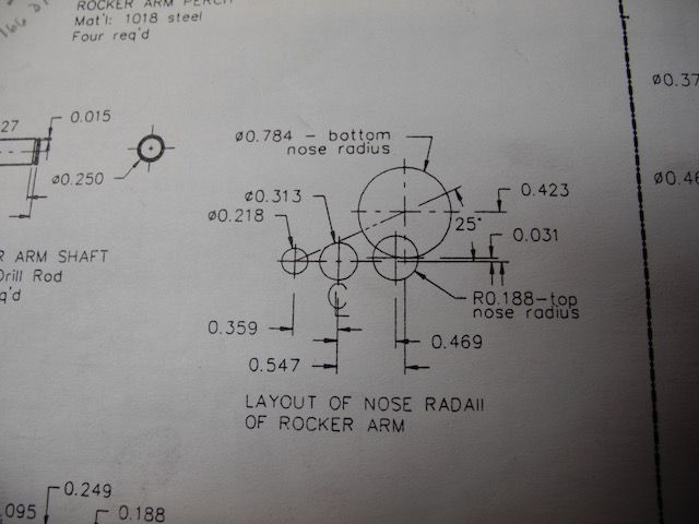
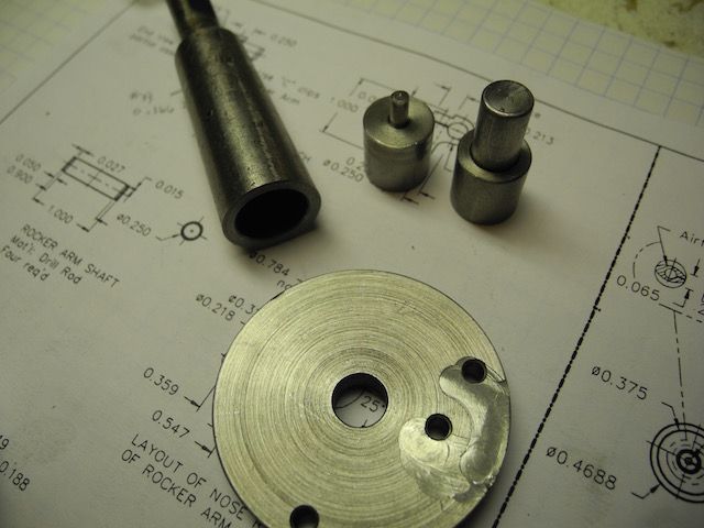
First off, the drawing detailed the radii centres for the nose and other important features. The 0.313 hole near centre is the pivot hole.
Each disc of material that was going to end up being a rocker arm was sliced off the stock, faced and dimensioned to thickness. The centre pivot hole was also drilled/reamed while in the lathe. They could then be put on the rotary table to have an index pin hole drilled and a clearance hole drilled for a machine screw hold-down.
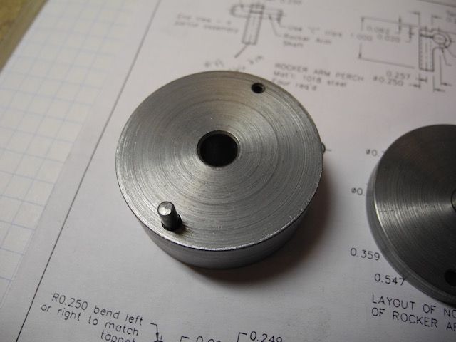
A lathe holding fixture was then made up with a matching centre pivot hole, index pin hole and a thread hole for the machine screw anchor. Here is the lathe fixture:
Now a radius cutter could be used to cut the groove in both sides of all the rocker blanks. After this each blank had a shallow curved depression all the way around the blank on both sides.
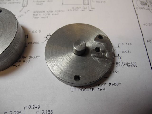
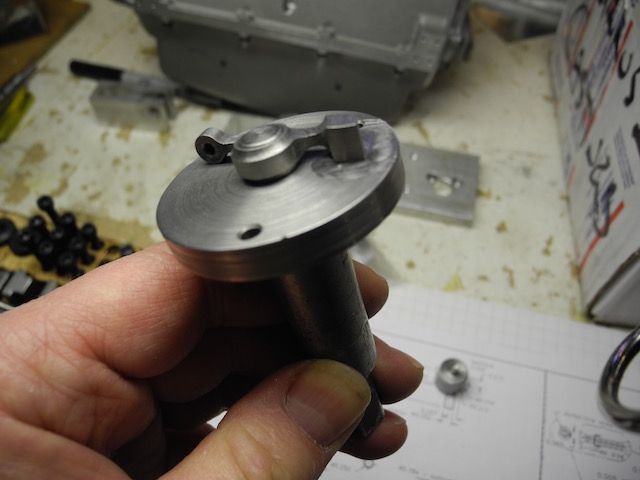
Some where in here I made a index plate for use on the rotary table. This plate has a centre pivot hole of the same dimension as the rocker arms, an index pin hole to match the one in the "lathe fixture" and two more to pickup the nose radii centres. Like this:
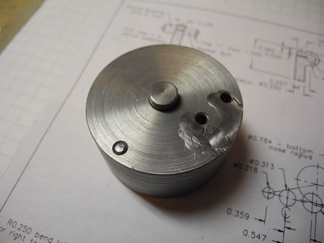
Here is another picture of the fixture plate on top of the "lathe fixture" with both index pins in place:
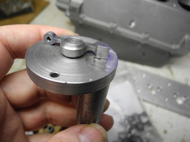
With the rotary table centred under the spindle I could now place the rocker arms on the fixture and on each of the critical centre points in turn to cut the arcs. There was some messing around with moving clamps for every operation and some planning ahead required to be sure there was something to clamp on. In the end I think it worked out pretty well - even the "spare" made it through without mishap.
All the best everyone!
Keep the questions coming - glad to be of any small assistance.
Charlie


