Author Topic: 1/4 Scale Cirrus MkI  (Read 30356 times)

Online Jo

  • Administrator
  • Full Member
  • *****
  • Posts: 15305
  • Hampshire, england.
Re: 1/4 Scale Cirrus MkI
« Reply #15 on: January 05, 2016, 08:37:37 PM »
Hi Charlie,

I thought you might find it interesting to compare your original Zimmerman castings to our "home cast" set  ;)

Jo
Enjoyment is more important than achievement.

Offline cwelkie

  • Full Member
  • ****
  • Posts: 195
Re: 1/4 Scale Cirrus MkI
« Reply #16 on: January 06, 2016, 01:15:03 AM »
Thanks Jo for "scaling" the 1/4 scale Aeronca!
Those Cirrus castings look up to the task. Some subtle differences but lots of "margin" to work with.  No oil pan tray though ... but you probably aren't going to fly it inverted anyway  ;)  (I don't think Ken-ichi bothered with one either; on his cut-from-solid version.)

Roger - For fun here is a photo of the "magneto" with a scale alongside and yes that's standard servo connector.  (Between the hall effect in the "mag" and the ignition module.


Offline Art K

  • Full Member
  • ****
  • Posts: 1767
  • Madison, Wisconsin USA
Re: 1/4 Scale Cirrus MkI
« Reply #17 on: January 06, 2016, 02:50:11 AM »
Charlie,
Seeing how far along you were I thought I'd missed it for a while. But I see you've just started. Wow...I've seen that Cirrus in SIC. I have to admit a fondness for aircraft engines. I will be following along.
Art
"The beautiful thing about learning is that no one can take it away from you" B.B. King

Offline cwelkie

  • Full Member
  • ****
  • Posts: 195
Re: 1/4 Scale Cirrus MkI
« Reply #18 on: January 06, 2016, 03:50:02 PM »
I'm humbled by such an talented and diverse group following along as I catch up with reporting progress on this build.  Thank you for the encouragement.

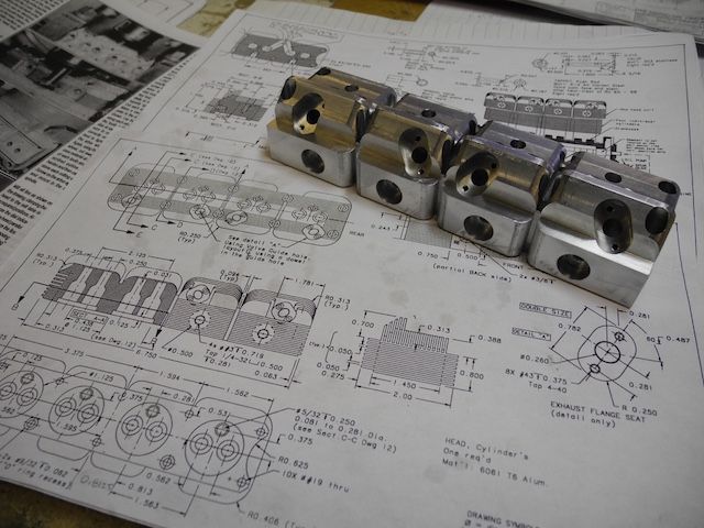
The cylinder head for this engine was (is?) the most intimidating piece for me.  The castings were bad enough due to their rarity but the head requires more machining operations than any other single part I've made.  A re-do would be ... let's just say, "frustrating".  For those that aren't familiar with this design, the head is one piece machined to provide the appearance of four individual heads.  It incorporates many angles, holes, rounded edges and many fins.

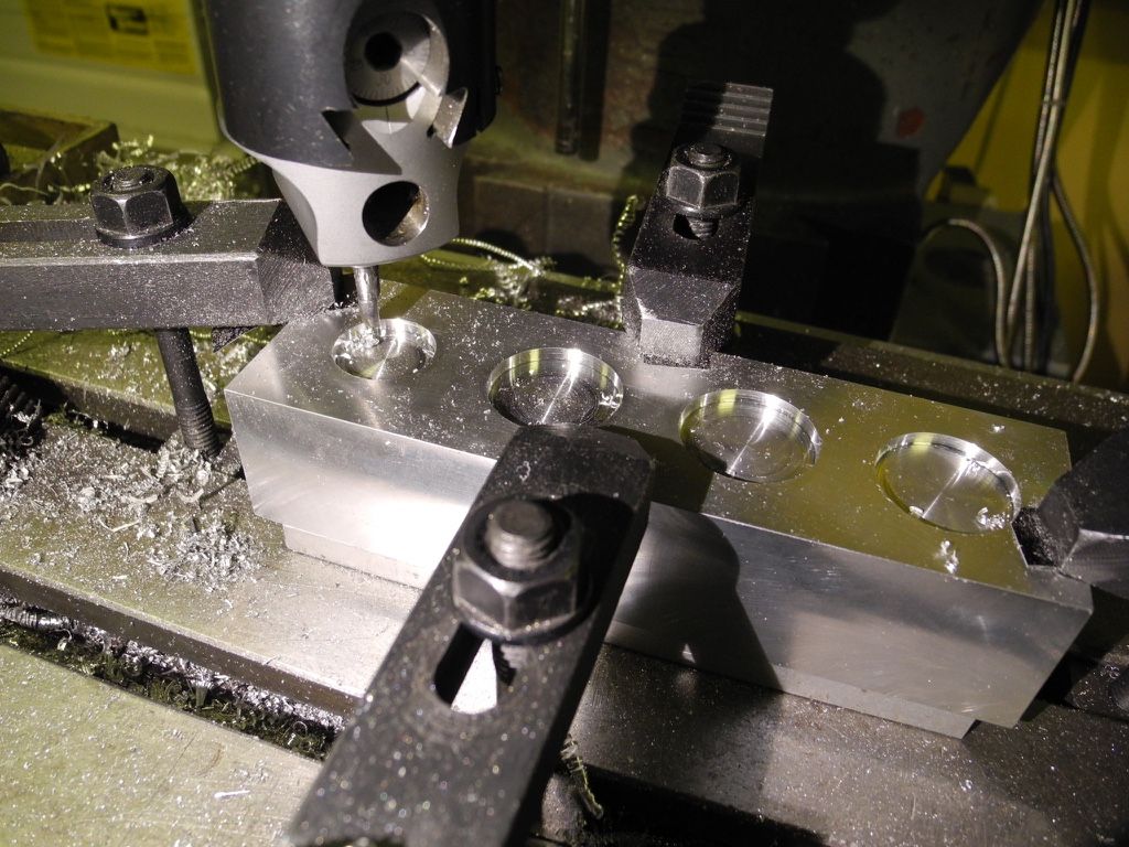
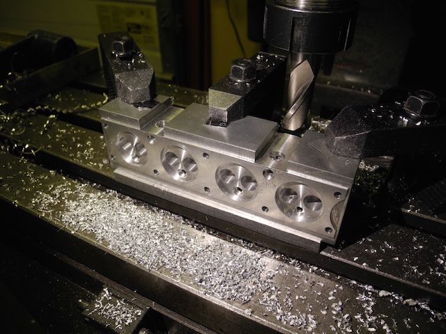
As shown earlier, I started with nice shiny block of 7075 that was finished to overall external dimensions.  What was  to be the top of the head was clamped to the mill table and the combustion chambers cut.  This was done with an end mill to start and sized with a boring head stepped over a few thou at a time.  Left over ridges were removed with discs of emery and a bore-sized rod spun in the mill with some lube.


The valve positions were then machined for receiving the guides.


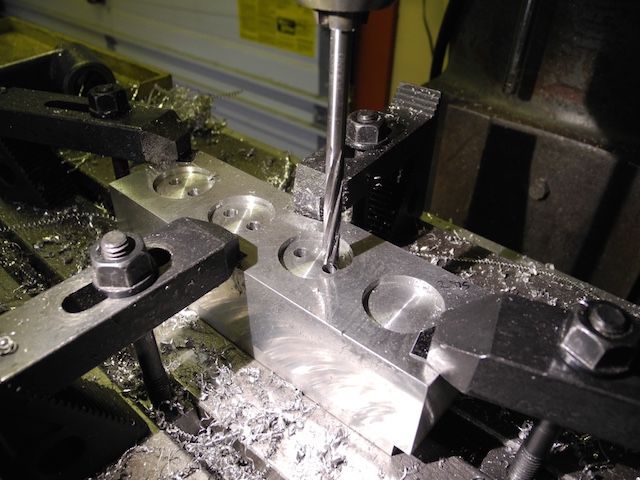
A ball-end mill was used to open the cavity below the guides and above the valve seats.  The seats are to be cut directly in the head on this design.


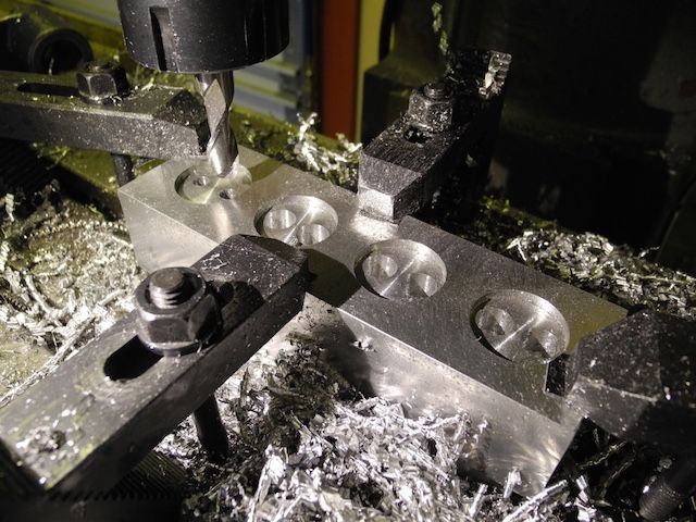
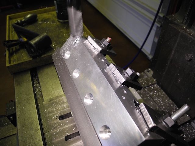
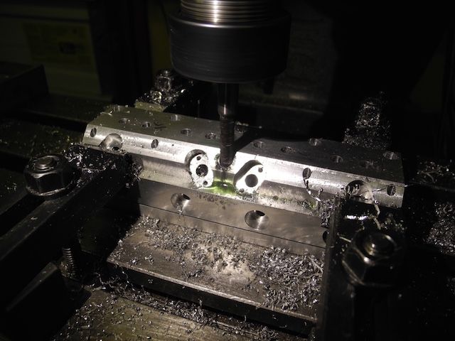
Next up were the "spark access holes" and the cylinder/head bolt locations complete with a couple o-ring countersinks for the bolts that pass through the siamese intakes.


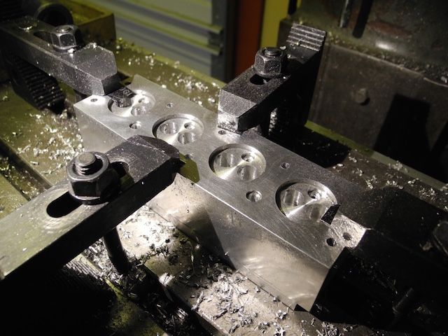
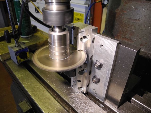
A relief was cut around the perimeter with an end mill.  The radius cuts on the ends were done with the saw made to cut the fins with shown earlier.  The intake ports were drilled and the "flange gap" around them milled away while the head was clamped on its exhaust side.


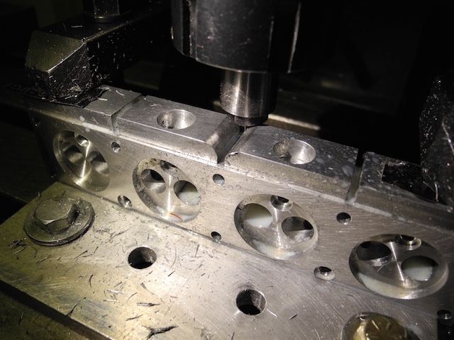
The connecting passages to each intake valve were then machined using an end mill and the intake manifold flange stud holes drilled and tapped.


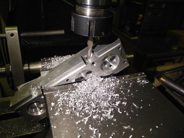
Now it was time to drill the spark plug holes and setup the adjustable angle plate to knock off a corner.


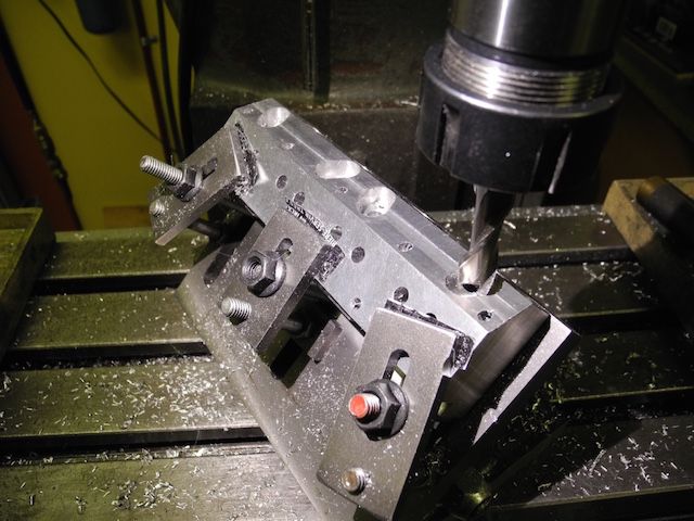
The angle plate setup was then spun to suit the exhaust flange locations so they could be done in pairs (i.e., two angled to the left; two to the right).  I was very glad that I'd taken the time to build the angle plate with enough accuracy to allow using the edges as references.


This photo shows countersinking the head bolt locations with a shop-made countersink. (Over an inch deep!)


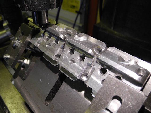
Now we're back to the right angle plate to saw the illusion-creating gaps between the virtually individual heads  :Lol:


It was now that the "rounding over" could begin ... virtually all the edges got the treatment from a D-cutter with the appropriate radius.  I was pleasantly surprised at the finish achieved off the cutter.


And that my friends is as far as I've gotten with the head ...


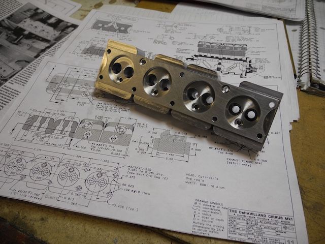
... it is a relief to be so far - so good.  The remaining four perimeter corners need rounding over as well but they are at a different radius and I'll use the rotary table for them.  I did make a spring loaded pointed pin that I can use in the table centre to pickup some blind, light layout punch marks.  That (fin cutting) saw blade is still awaiting its workout as well.

That's as far as I got before breaking my (dominant!) wrist just before Christmas ... no shop time for awhile yet.  (I'll be really  :censored: if the healing delays my motorcycle season start!)

In the meantime, I'll take a few photos of the other parts completed so far (the rocker arms and their posts are particularly neat - in design) and get them posted.

Thanks again for being there!
Charlie

Offline joe d

  • Full Member
  • ****
  • Posts: 400
  • Montreal, Canada
Re: 1/4 Scale Cirrus MkI
« Reply #19 on: January 06, 2016, 05:13:08 PM »
Lordy lordy there sure are a LOT of set-ups in  that one piece!

Very much enjoying seeing this one, thanks Charlie.

Joe

Offline vcutajar

  • Full Member
  • *****
  • Posts: 2555
  • Marsascala, MALTA
Re: 1/4 Scale Cirrus MkI
« Reply #20 on: January 06, 2016, 05:14:20 PM »
Wow Charlie, that head is really looking great. Thanks for showing all the steps.

Vince

Online petertha

  • Full Member
  • ****
  • Posts: 784
Re: 1/4 Scale Cirrus MkI
« Reply #21 on: January 06, 2016, 07:25:31 PM »
Looking good! I'd like to see a shot of your corner rounding (what you call D-cutter). I bought one for fear a home-brew would not work well. Assume its a single edge from oil or water hardening tool steel?

Offline cwelkie

  • Full Member
  • ****
  • Posts: 195
Re: 1/4 Scale Cirrus MkI
« Reply #22 on: January 06, 2016, 11:32:13 PM »
Hi Peter - here are a couple photos of the round-over cutter.  You're right, it  was made as any usual D-cutter and then hardened and tempered.  I used 3/4" O1 ... fresh out of 5/8"!  This time I remembered to leave a round section so I could measure approach to half-diameter ... as mentioned it presented a better than anticipated finish (please don't ask about feeds and speeds though - don't right that stuff down  :shrug:
Just holler if you've any other questions.


And .. just because I felt such a fool for taking so long to figure out how to centre a "blind reference" on the rotary table here are some photos of the widget I threw together for that.  It is intended to pickup a centre punch/layout mark on a surface that is clamped to the table - kinda like a centering spigot that doesn't go through a hole.  It reuses an old MT2 Drill shank that I've bored to 0.5" to take a wide collection of such spigots.  This one just has a very short 60' pointy end and a spring under it.

Perhaps it's a helpful idea ...probably old news to the masters out there though.


Cheers
Charlie

Offline tvoght

  • Full Member
  • ****
  • Posts: 1003
  • Indiana
Re: 1/4 Scale Cirrus MkI
« Reply #23 on: January 06, 2016, 11:38:15 PM »
Thanks for showing the tools, Charlie. Both are interesting to me. I'm enjoying your build. Like others here, I admire the Cirrus very much.

--TIm

Offline 10KPete

  • Full Member
  • ****
  • Posts: 1606
  • Nordland, WA, USA
Re: 1/4 Scale Cirrus MkI
« Reply #24 on: January 06, 2016, 11:40:27 PM »
That's a great idea!  :whoohoo:  I've been noodle-ing on how to center stuff on my RT once I have the mill going and that idea
is going in the tool box. :praise2:

Pete
Craftsman, Tinkerer, Curious Person.
Retired, finally!
SB 10K lathe, Benchmaster mill. And stuff.

Offline Don1966

  • Full Member
  • *****
  • Posts: 6818
  • Columbia, MS
Re: 1/4 Scale Cirrus MkI
« Reply #25 on: January 06, 2016, 11:47:27 PM »
Beautiful results on the head Charlie and love the use of the D bit.

Don

Offline b.lindsey

  • Global Moderator
  • Full Member
  • *****
  • Posts: 13860
  • Dallas, NC, USA
    • Workbench-Miniatures
Re: 1/4 Scale Cirrus MkI
« Reply #26 on: January 06, 2016, 11:56:09 PM »
That head is most impressive Charlie. Must be quite a relief to get it done without any mishaps. Beautiful work!!

Bill

Offline Dave Otto

  • Full Member
  • *****
  • Posts: 4711
  • Boise, Idaho USA
    • Photo Bucket
Re: 1/4 Scale Cirrus MkI
« Reply #27 on: January 07, 2016, 12:53:21 AM »
Yes the head is looking real nice! Lots of operations in that part.

Dave

Offline cwelkie

  • Full Member
  • ****
  • Posts: 195
Re: 1/4 Scale Cirrus MkI
« Reply #28 on: January 08, 2016, 07:59:00 PM »
Thanks all - yes, it is nice to have the head this far along without mishap or unintentional "decoration".

As promised earlier, I've taken photos of the other parts already completed and will post them as well.  They probably won't be as interesting (no setups) but at least all the bits will be in one place so-to-speak.

I'll start with another part that required a number of setups, blind holes and a few tense moments with tiny drills.  I decided to use a two-jet carb design that was publish in SIC years back.  I think it was by Jerry Howell.  No real reason for doing it different than the Zimmerman carb; just wanted to build this two-jet example.  Time will tell how it works on this engine.  (I did revise the venturi size to be in-line with that used on the Zimmerman drawings ...)


The oil pump is driven straight off the back of the crankshaft.  A tiny cross-pin fits into a socket head screw in the back of the crank.  The tapered ends of the pin engage the internal angles of the screw.  Simple universal joint ... The gears were cut using a shop-made hob - 48DP - aka "tiny".  The inlet and outlet nipples are to plan but I don't think they'll stay.  The pump body is threaded so I reckon they'll be changed to metal tube fittings in the end.  These are good for testing and run-in though.


The dipstick is a simple bit but a nice distraction as simple bits can be.  The blade hasn't yet been "calibrated" ... it was the stainless steel spine of a wiper blade in a past life.


These are the clamps that hold two crankcase breather tubes in place either side of the forward crankcase.  They were a fabrication from solid and tubing; silver soldered/brazed together.


This is the breather itself.  It threads into an angled hole on the front cover just above the crankshaft.  It too was a fabrication; two tubes and a bit of solid all silver soldered/brazed together.  There were some anxious moment using some relatively large cutters on pretty small parts.  I only had to make two of these to get a keeper.  The aluminium cap unscrews to allow oil to be added to the crankcase.


I'll leave off here for the moment ... a few more photos of the valve train pieces and cam gears and then I'll be caught up.
Charlie


Offline cwelkie

  • Full Member
  • ****
  • Posts: 195
Re: 1/4 Scale Cirrus MkI
« Reply #29 on: January 09, 2016, 04:01:22 PM »
Okay - more more go and then I'll be caught up until I can get back into the shop.

Here is a "family picture" of some of the valve train pieces.  Rocker arms; their posts, shafts and bushings.  The rocker arms started as full diameter discs that were drilled and reamed for the pivot hole and the various radii.  The side radii were cut on the lathe; each side of a disc in turn on a fixture.  The rotary table was then used to cut the arcs in stages on another fixture that used index pins in each of the reference radii holes.  The posts also started as discs and were a combination turning, rotary table smiling exercise as well.  Yet another fixture on the table to finish the upper radius.


Here is a photo of one assembly resting in it's ultimate destination on the as yet unfinished cylinder head.


A few more bits and bobs ... tappets, valve spring retainer cups, tappet oil seal retainers and the oil pan plug.


Here we have the camshaft gear train.  I made the camshaft gear adjustable over a few degrees in part for the practicality but mostly because I think it looks right.  These gears were also cut by hob - 32DP.


A closeup of the engraving marks done by a tiny ball cutter in the mill (while on the rotary table of course).


Here's the backside of the camshaft gear.  I've left broaching the keyway in this gear until it's position can be determined on assembly.


Thanks for looking in - sorry for the lack of setup pictures to go with the last lot ... consequence of waffling over posting the project.
Charlie


SimplePortal 2.3.5 © 2008-2012, SimplePortal