Lady Godiva Rides Again - Episode 7
Roy Ozoufs Coventry EngineFiddly BitsThe valve action has all manner of small parts which move in mysterious ways.
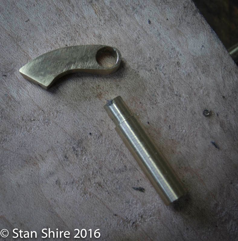
The rocker bracket was laid out with a print of the drawing.
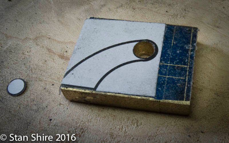
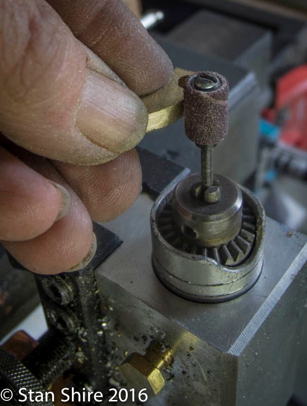
After roughing it out with a jewelers saw, much sanding and filing followed. Here, the Foredom Flex shaft tool in its holder.
Then to Oliver
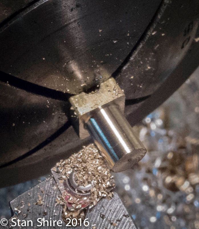
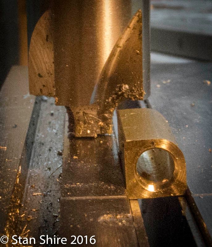
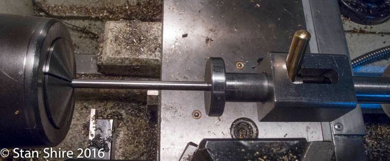
A tube was turned down at one end to fit in the bracket hole for silver soldering.
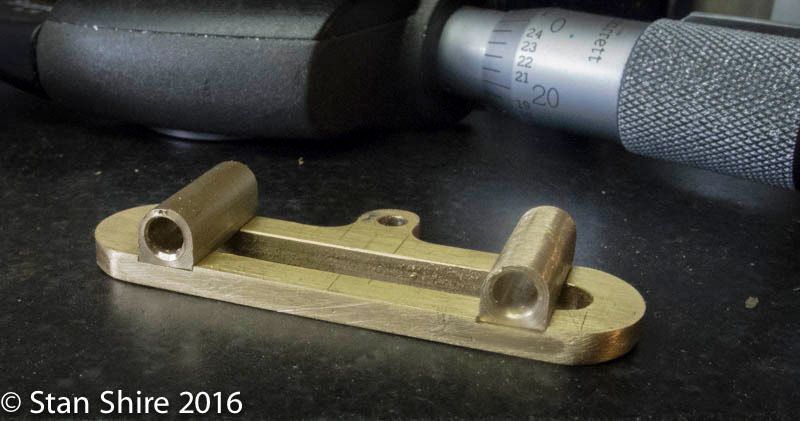
Next is the rocker shaft. Again two parts to be silver soldered. First, the rotary table to round the ends.
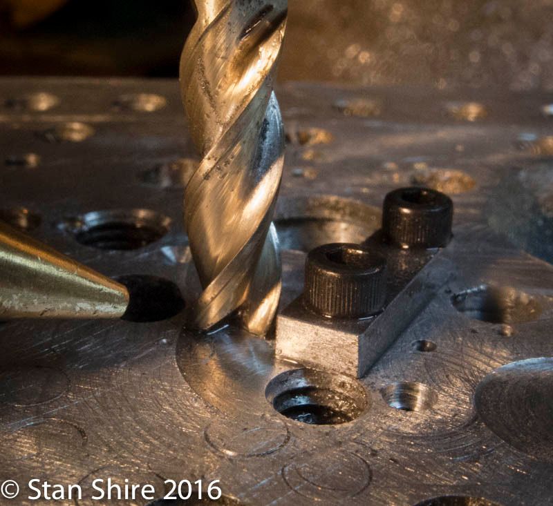
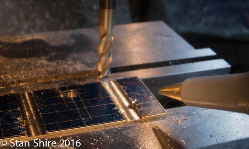
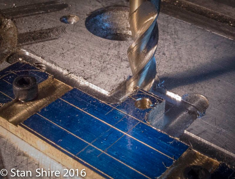
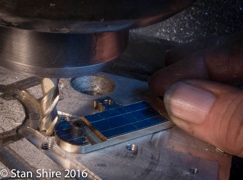
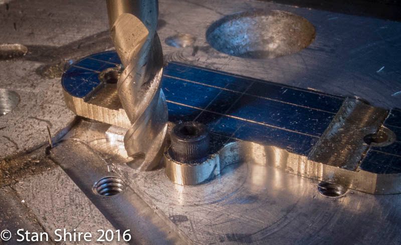
The valve rod end first has a slot milled with a center-cutting end mill (.093)
Then to a square collet to round, drill and tap the other end.
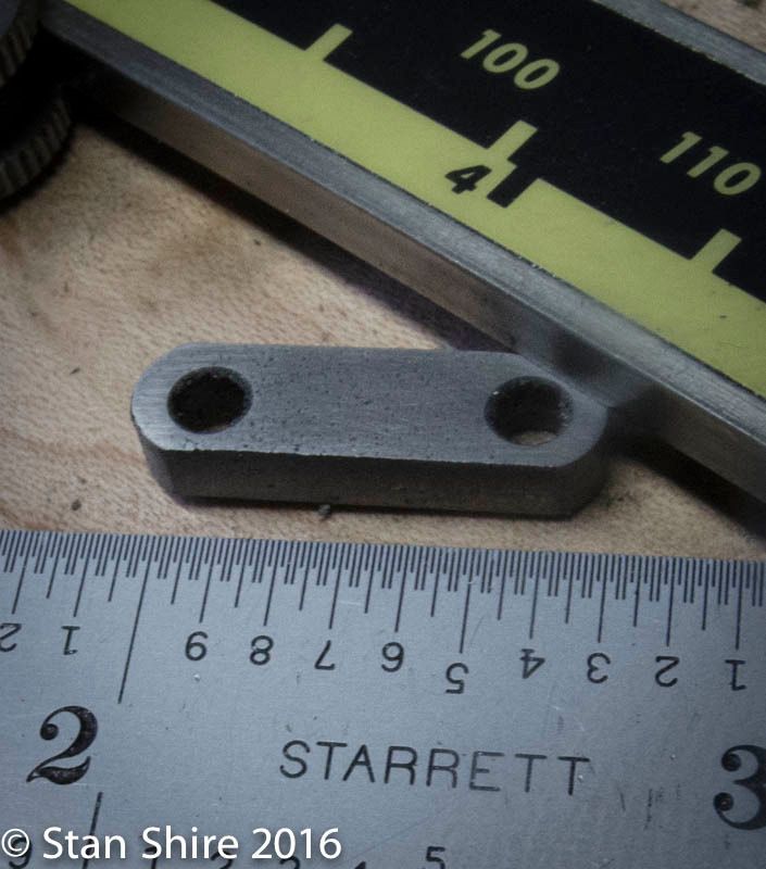
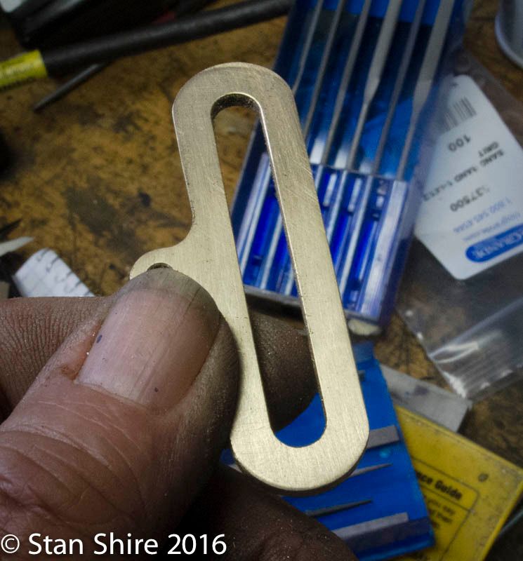
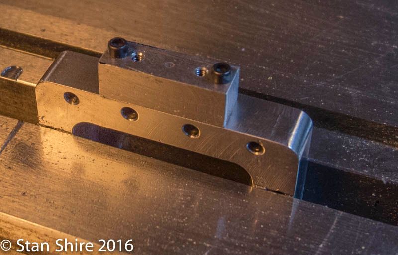
The link, is another built-up part. It moves up and down on parallel rods which pass through the link guides.
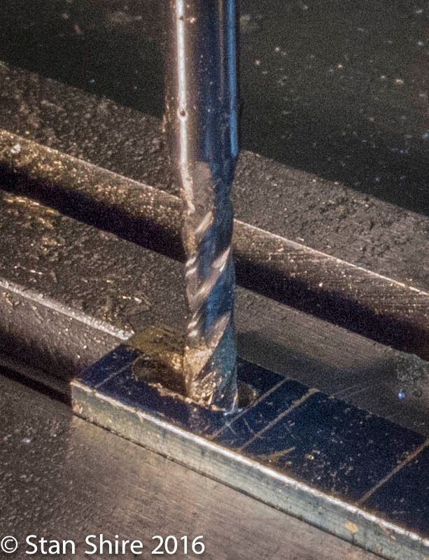
Starting with a piece of brass flat bar, it was face milled to thickness.
Then, small recesses were milled to locate the guides for soldering.
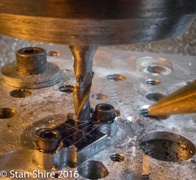
Drilling and rounding.
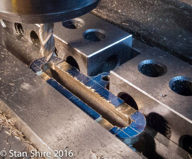
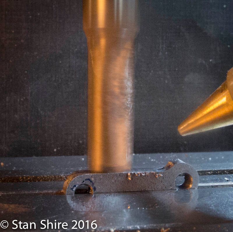
And, slotted.
A bit of filing finished the link.
Starting with .25 brass square bar, the top was rounded.
Positioned for soldering
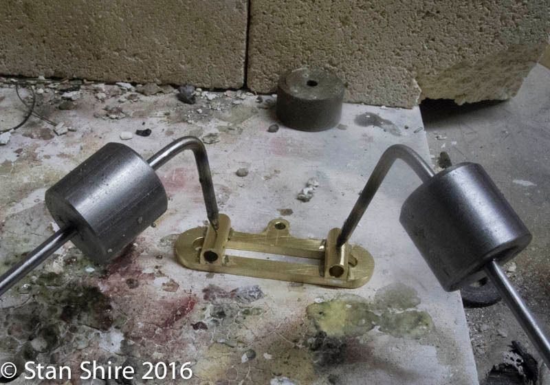
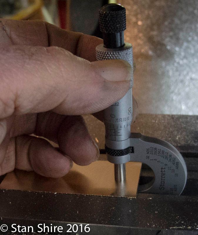
Next, the guide rods. To ensure that they were the same length, I used the Cletus-built,close-enuf, bolt action tailstock stop. Amazing! It worked so well and was so much fun that, I couldnt stop at the required two rods.

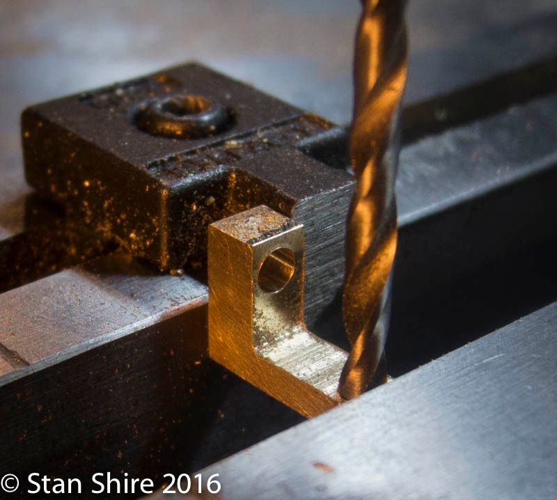
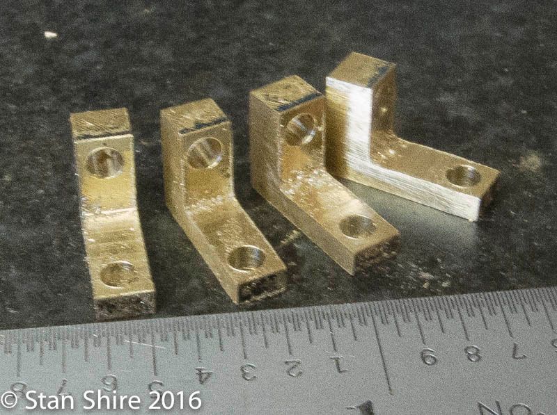
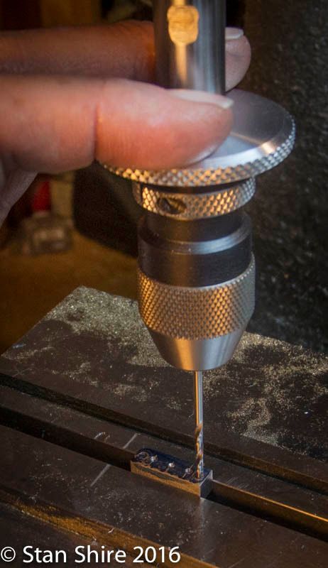
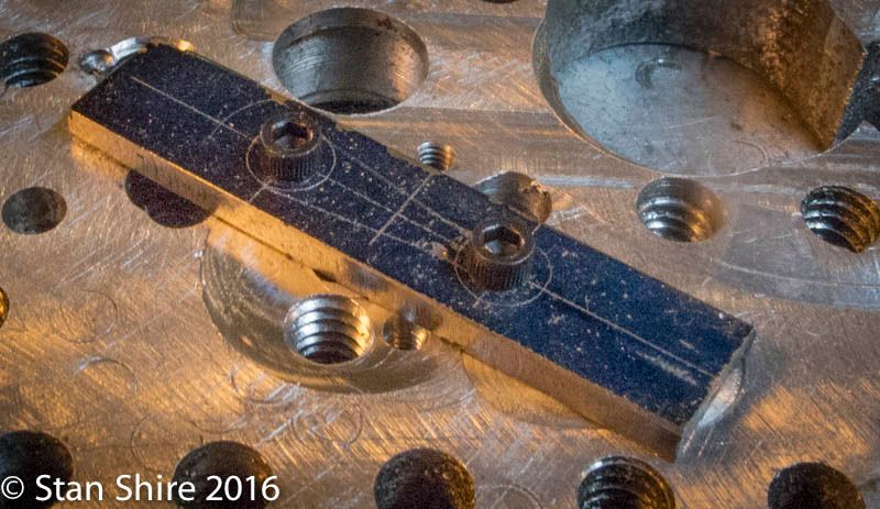
Then the tiny, threaded brackets for the guide rods. First, milled, then cut.
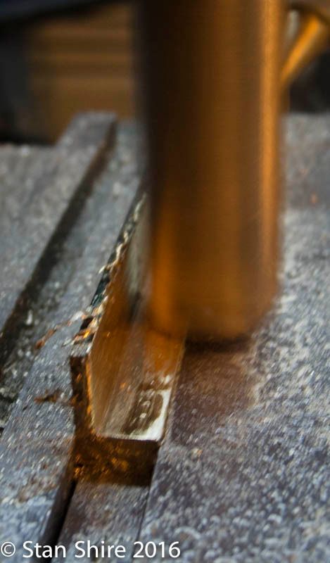
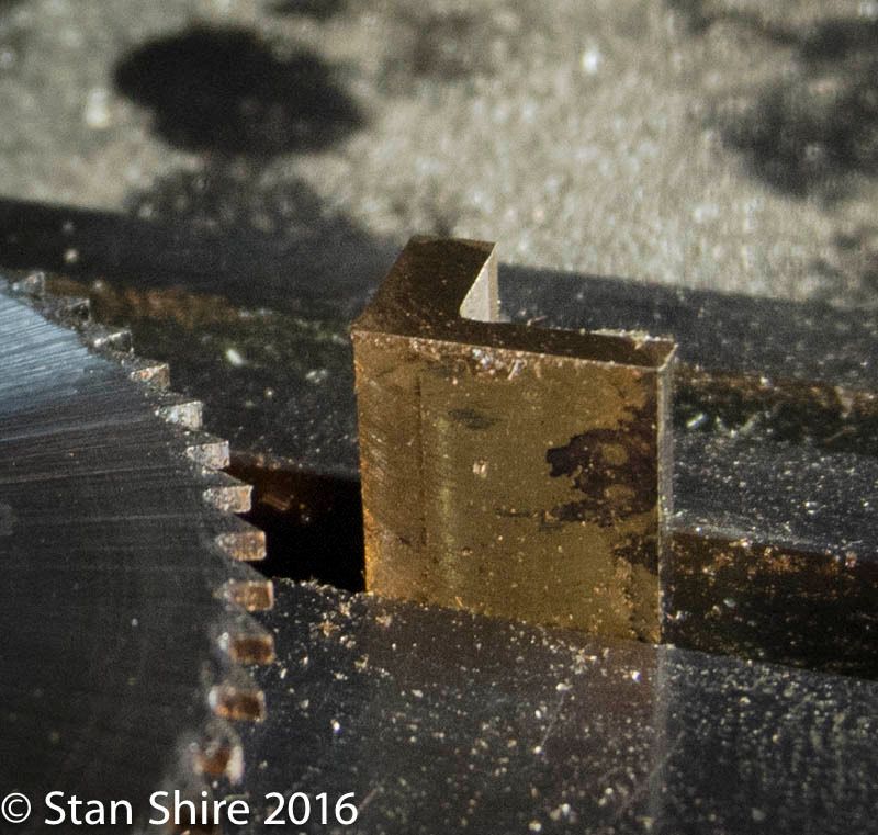
Two extra (just in case I did a Bozo op)
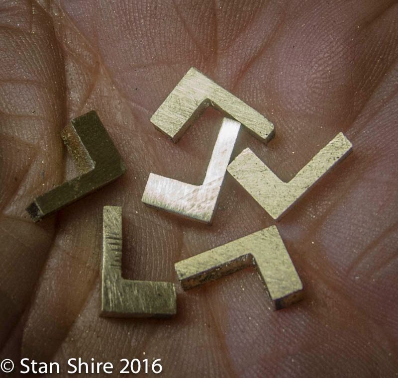
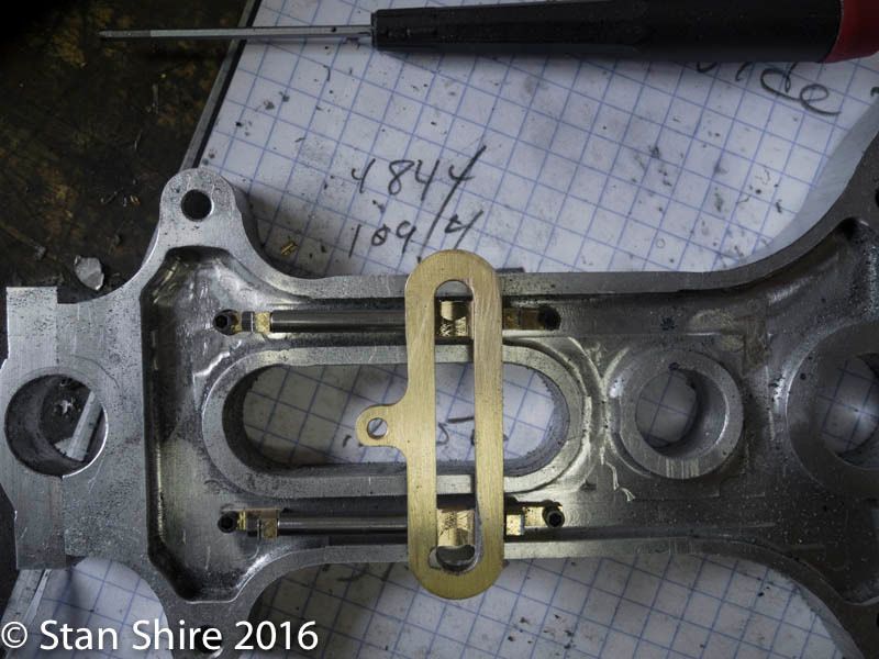
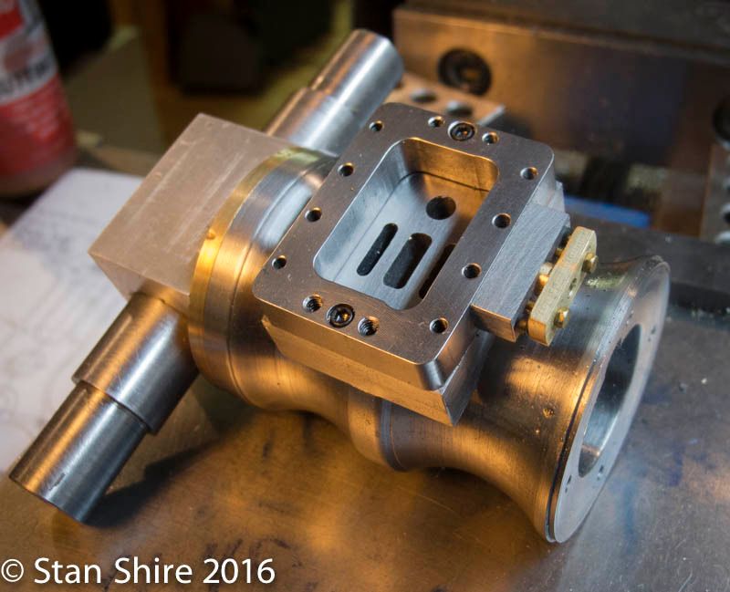
The brackets, guide rods and link, screwed to the side plate.
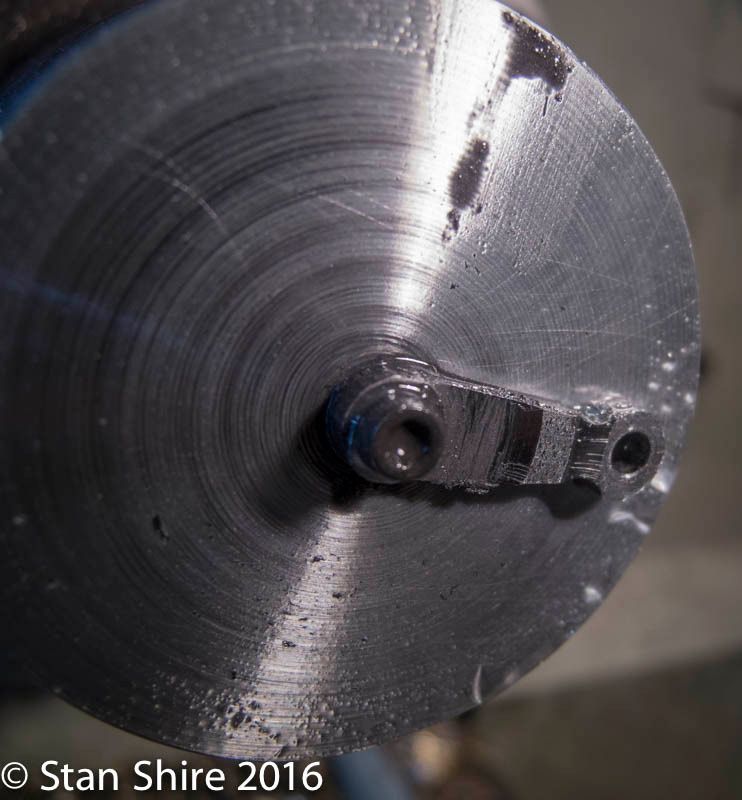
Drilling the steam chest, gland mount.
In position with working hardware.
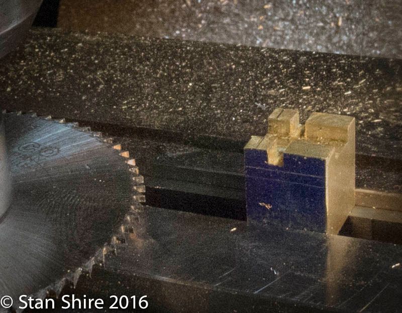
I though Id start with a large chunk of brass for the valve as its easier to hold.
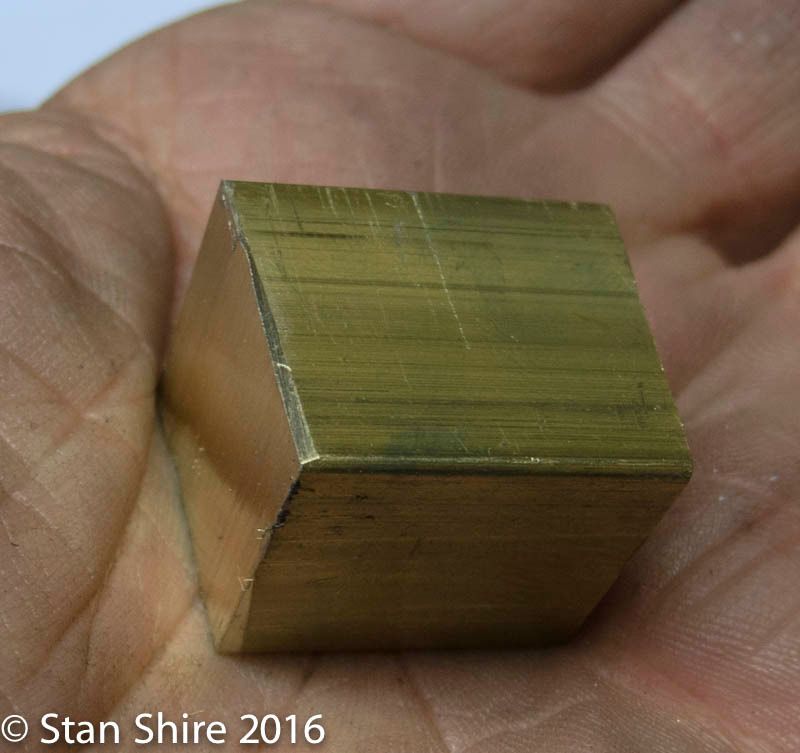
Milled and cut off.
And, in position
Now, onto the rocker arm, laid out and screwed to the rotary table.
Cranking the table around to the layout lines
And the, addressing the sides
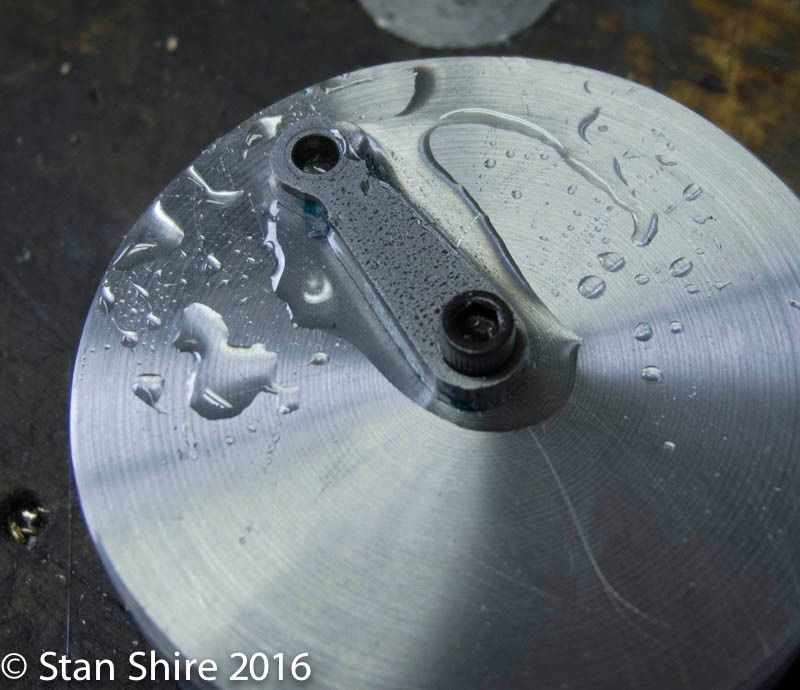
The arm had a turned boss. I turned a tiny faceplate, screwed the arm at center and melted some Crystalbond to hold the part.
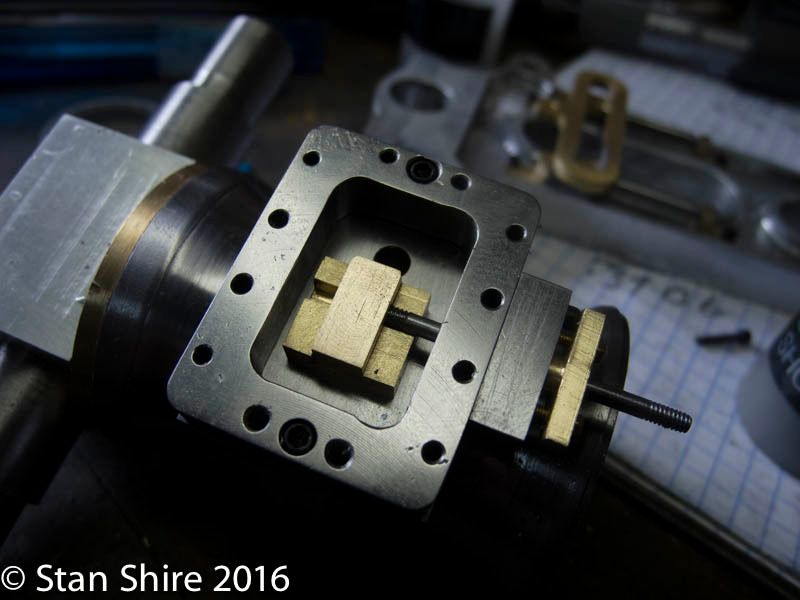
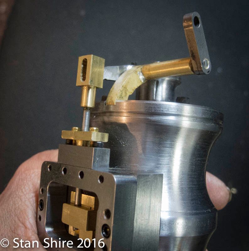
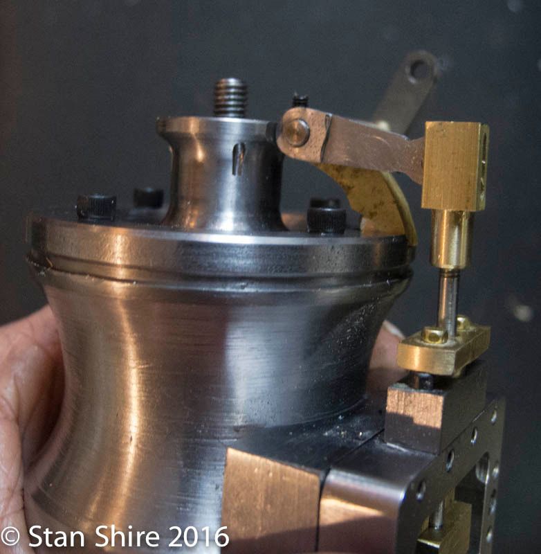
Beginning the assembly. Now it may be easier to see how the valve motion works. The part not shown is a die block with floats on the rocker arm and travels in the link slot.
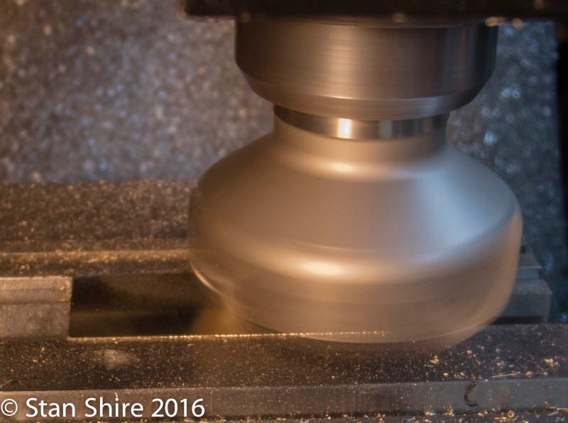
Next, smoothing out the side plates and the flywheel.


