Thanks Jo - maybe I should mill a pocket on the top to make sure tools stay there when put down... Seeing as I've used the front end of the cross slide for keeping drills lying around, I'm sure the flat top will see a lot of use

Nearly a month without shop time... At least a bit today.
I had a bit of time to think things though, and decided to use a "Metal Removed" scale, and doing some quick calculations, decided on a 0.05mm scale. On a 38mm diameter dial - for which I have stock, that leaves divisions that's nicely spaced as well - at about 1.5mm apart for the 80 divisions needed on the dial. Making a vernier collar to take things down to 0.01mm based on the dial's divisions is also easy; that runs to "100 divisions" at 1.2mm spacing, so also easy to make and see.
First off, the vernier collar - just some 40mm aluminium bar faced and turned down to 38mm OD:
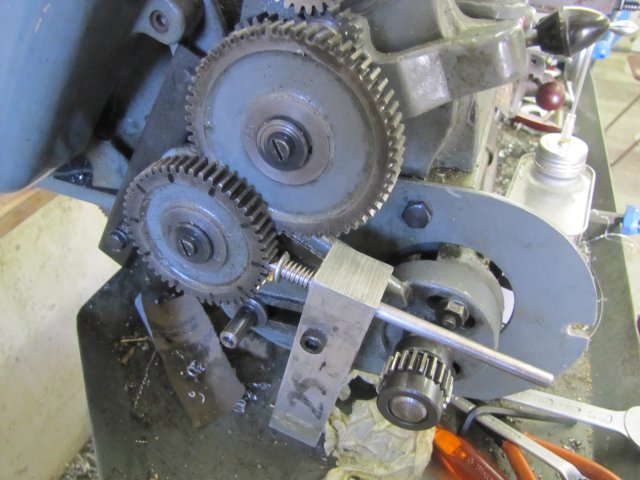
Then I set up the lathe's banjo with a 60 tooth gear on the spindle side, driving a 30 tooth gear coupled to a 50 tooth gear to use as the index, along with the crude detente I made for a
similar job at Tel's suggestion a while ago. The 50 tooth gear even still has the permanent marker markings I made on it

:
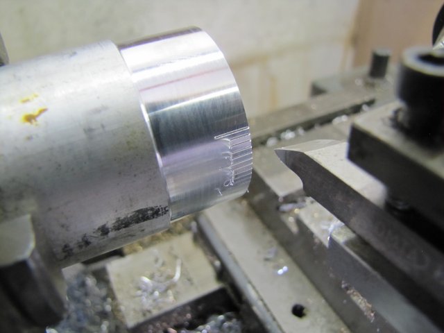
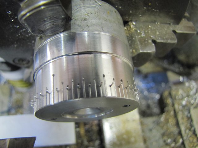
I used a very sharp 60
o threading toolbit mounted side-ways to cut the markings about 0.1mm deep. In theory, only 5 vernier markings is needed for the layout I chose, but I cut 10, with a long marking in the middle for 0. When I made the scale for my rotary table, I used a similar layout, and have found it extremely useful for working on either an in-feed or out-feed:
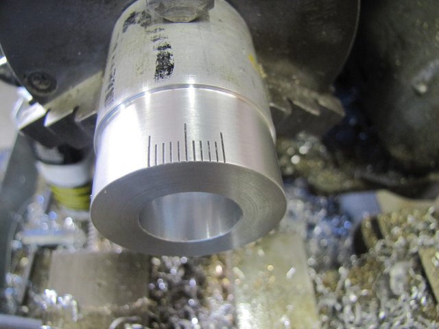
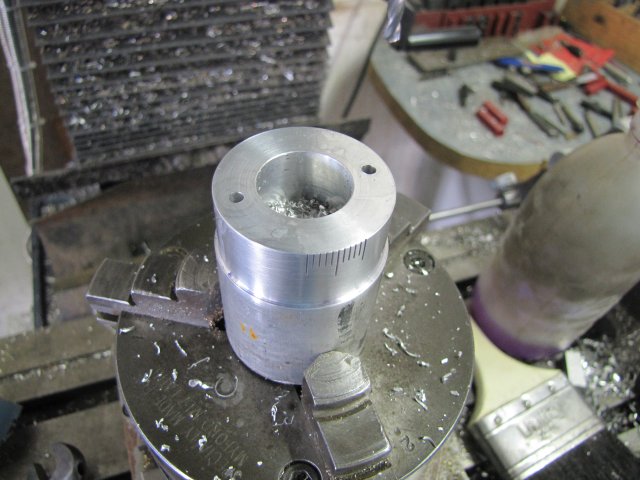
Next I bored out a hole in the center - this is to clear all the working bits of the cross slide once mounted to the cross slide bracket. The engravings also got a tidy-up with a bit of sandpaper and then Scotch-Brite to dull the finish a bit - in use, I don't want the scale to be shiny, as that makes it more difficult to read under the shop lights:
The lot was taken to the mill, mounted on the rotary table (convenient to mount the lathe chuck in my shop), the center of the hole located, and the table rotated to get the zero-line in line with the mill spindle with the X axis at zero and using a small drill to match up to the line. Just me being lazy to get the workpiece oriented so that the mounting holes would come out fairly square to the zero line on the collar. Mounting holes drilled at 3mm - after this they were counter bored to 6mm to allow room for M3 cap screws to go below the surface:
The vernier collar was then parted off.
The same bit of stock was then turned down to 38mm to about 6mm away from the chuck, and the rest toward the chuck just skimmed to clean it up. Then a 40 tooth gear was marked with permanent marker to show the gaps where the 0/1/2/3 mm marks must go (the 0/2 and 1/3 are in the same location) - those have the extra dots on the gear hub, and the 0.5mm spacings are the two without markings on the gear hub. The 0.1mm markings would come at every second gap in the gear starting from the One markings, and the 0.5mm markings from every second gap starting from the gap just after the One markings:

Actually, it's easier to do than describe - the 40 tooth marked gear was mounted in place of the 50 tooth one shown earlier, the detente adjusted, and the motions followed. All done here:
The 0.5mm marks are a tad too short

- that's what one get by just eyeballing things.
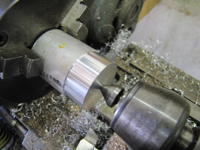
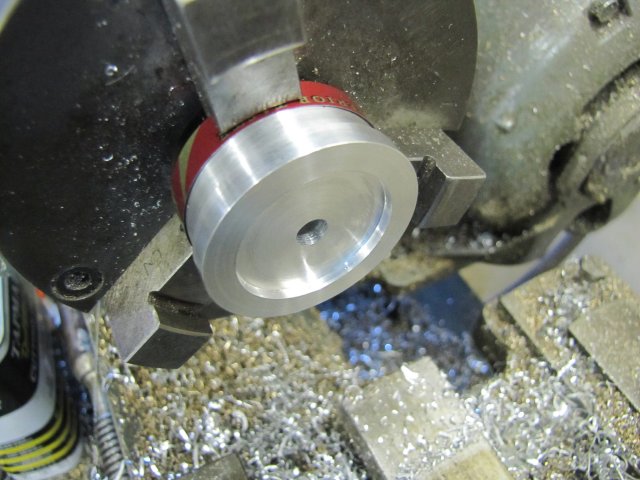
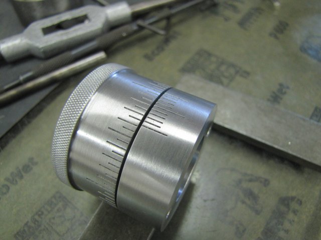
The center of the workpiece was bored to 12mm about 15mm deep - this is for space for the pressure spring I want to use- and then drilled right through 6mm to allow for the feedscrew threads. The index markings was cleaned up, and excess stock sawn off on the bandsaw. Then it was mounted back on the lathe - this time using the chuck's outside jaws and a bit of aluminium can strip for protection. There's two reasons I used the outside jaws: 1. The "curve" on the inside jaws when chucking up like this is bigger than the workpiece, and together with the can strip, it provides good clamping force without damaging the markings. 2. My three jaw chuck's outside jaws are pretty accurate across the clamping range. If that wasn't the case, I'd have used the 4-jaw and chucked up the workpiece in that. The back of the workpiece was then turned down to get rid of the bandsaw markings, and then bored to make a friction surface / locating ring that will match up to the actual handwheel later on:
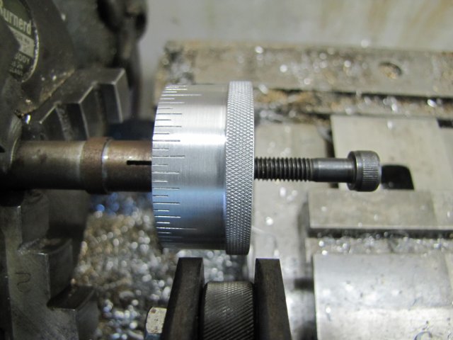
My scissor knurling tool cannot get close enough to the chuck to use in any of the previous operations, so I mounted the workpiece on a home-made expanding mandrel to get the needed distance and gave it a bit of a knurl with 0.5mm diamond knurls. I'm well aware that no medals will be won for this job - according to "judging criteria" I've seen, it's too fine a knurl for this size of job, and the tops are not "well-formed and sharp"... A straight knurl is actually what's required for this application, but I've not gotten around to get a wheel for that, and didn't feel like making one. I could just have indexed a straight knurl similar to the scale engravings, but that's just too much work for a lazy sod like me. This fine knurl, only partially done to depth is easy on the fingers in use, but gives a good grip even with oily fingers, so it's practical in use, and completely adequate for my needs:
For today's work, I ended up with this lot - not much, but extremely gratifying:
Kind regards, Arnold


