The crankshaft comes as a substantial SG Iron casting almost 14" long
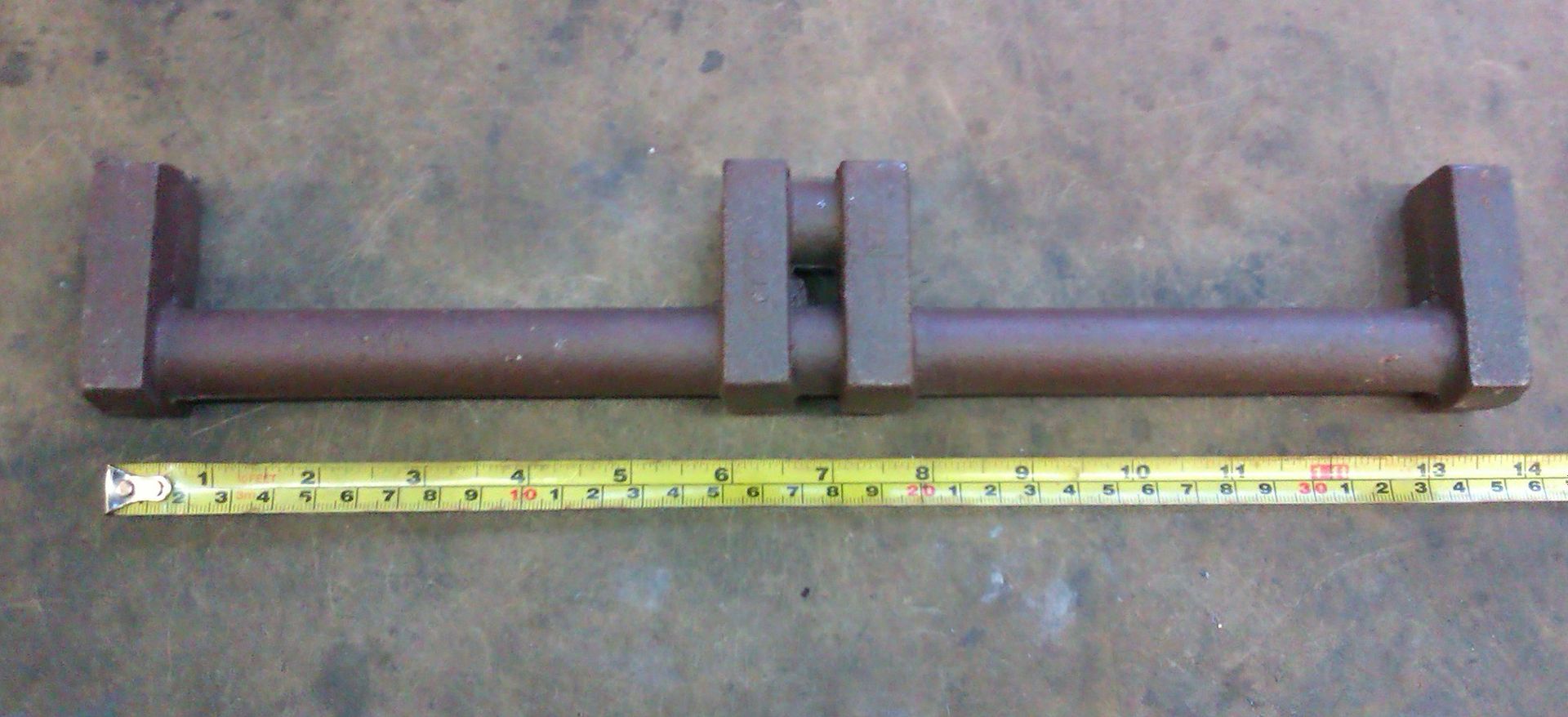
The first thing I did was mill the sides of the webs to give me a flat plane to work with and also skim the two ends. Using the mill table as a surface plate I laid it flat down and marked the ctr line, then clamped the casting to an angle plate and put on lines at 90 degrees just to act as a guild.
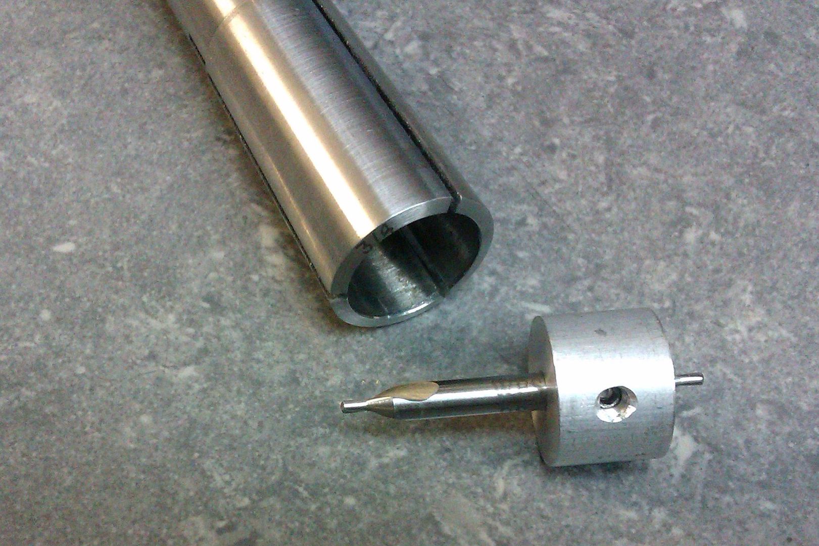
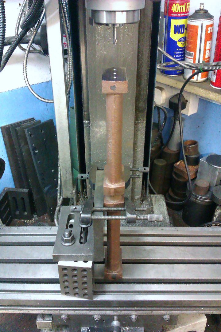
The crank was a bit to long to fit under the mill with a drill or collet chuck so I knocked up an adaptor to hold a ctr drill that could be held in a MT3 taper collet.
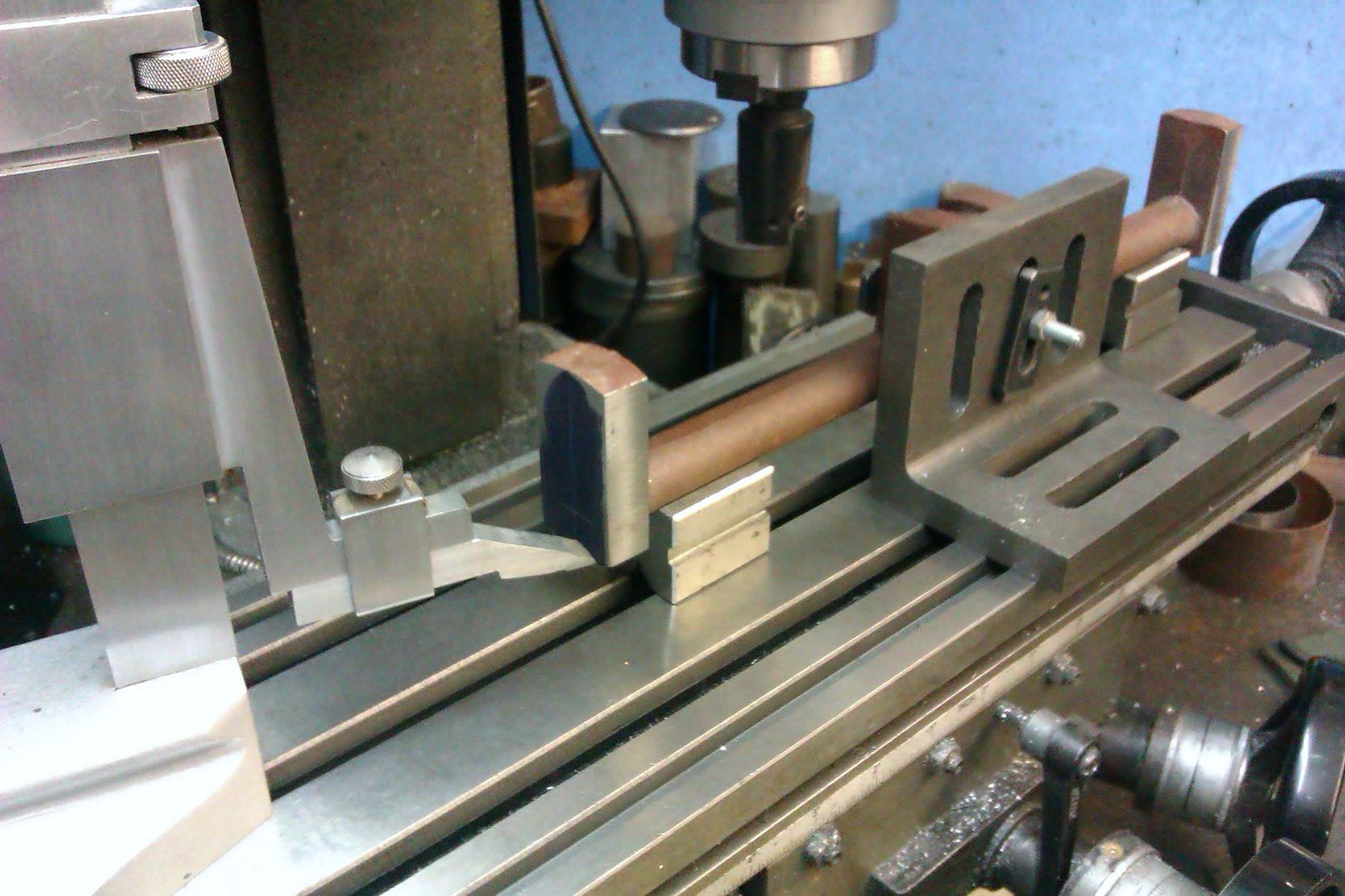
I trued up an angle plate and clamped the flat webs to that, picked up my lines and then used the DRO to position the three ctr holes and repeated for the other end. By keeping the same side of the webs against the angle plate I could ensure that both sets of 3 holes were perfectly in line so no risk of a twisted crank.
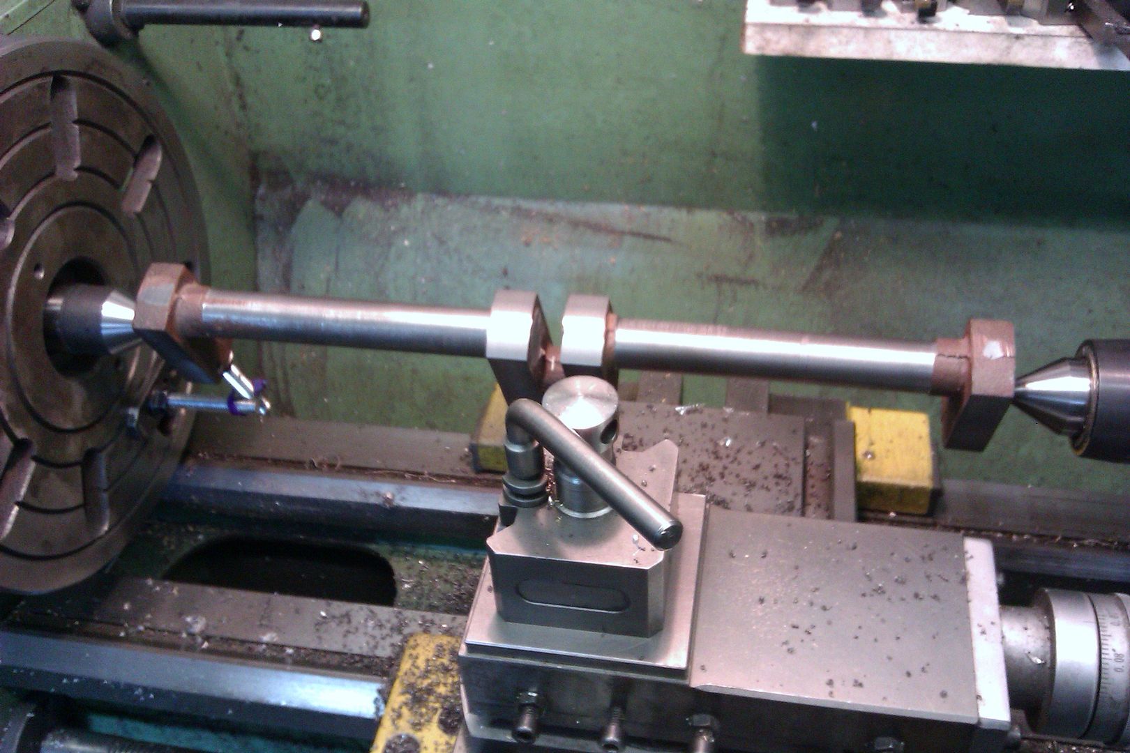
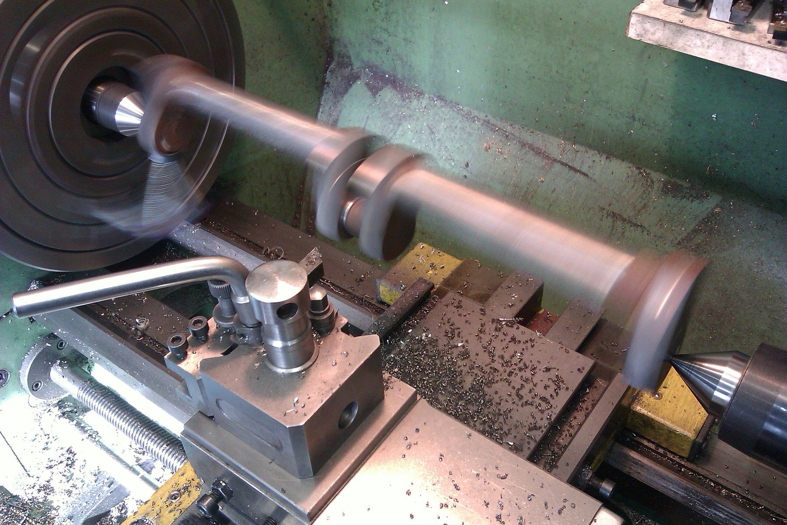
Over to the lathe and I took a couple of roughing cuts off the main shaft to get the mass down and reduce any imbalance to a minimum. Then using the middle of the three ctr holes radiused the ends of the webs.
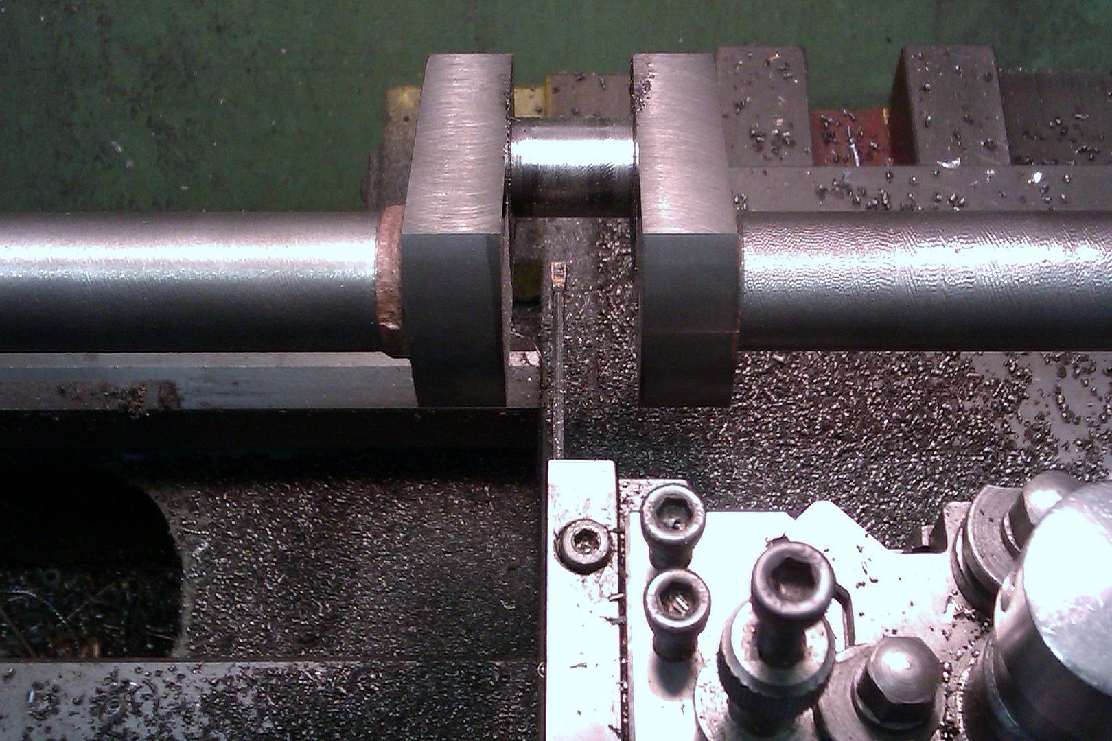
I have a tool that takes the 55deg rhomboid shaped tips that is reversible so I get a left and right hand tool in one and used this to machine down the inner face of the webs.
[youtube1]https://youtu.be/18pocye3leM[/youtube1]
Its a nice rigid tool but a bit to wide to remove all the metal in the middle.
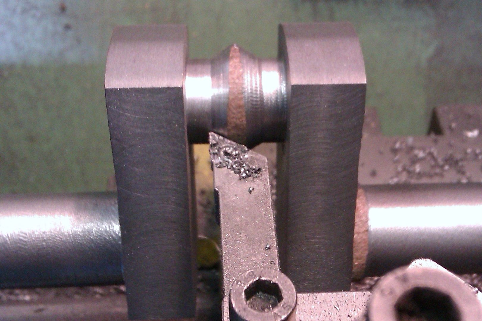
So had to use a parting tool for the last cuts, I keep one of the 2mm wide tips that has had the middle ground away with a dremel as this reduces chatter and leaves a reasonable fininsh as the tool is wound from side to side taking fine cuts.
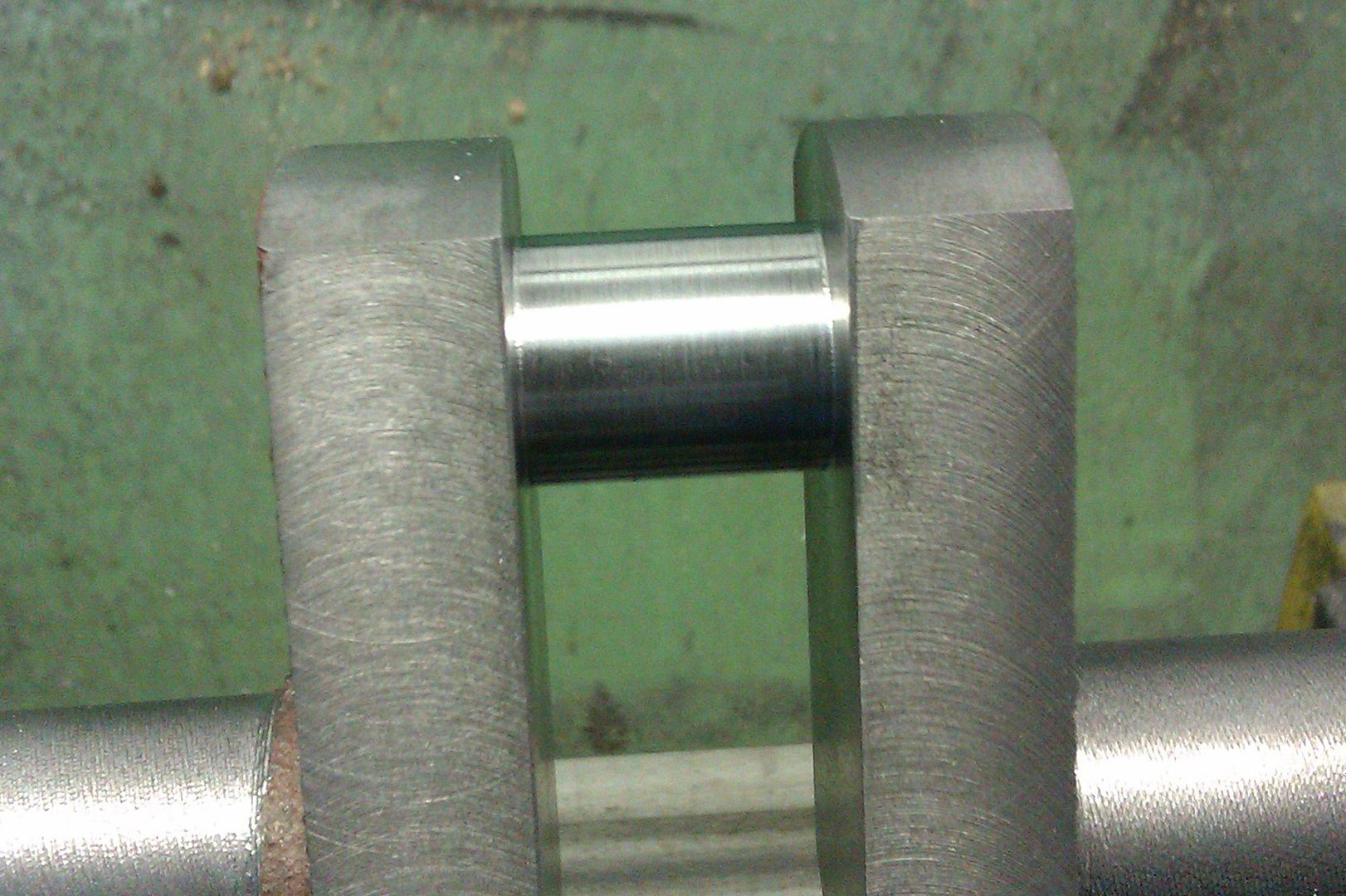
A bit of final finishing and it look reasonable to me.
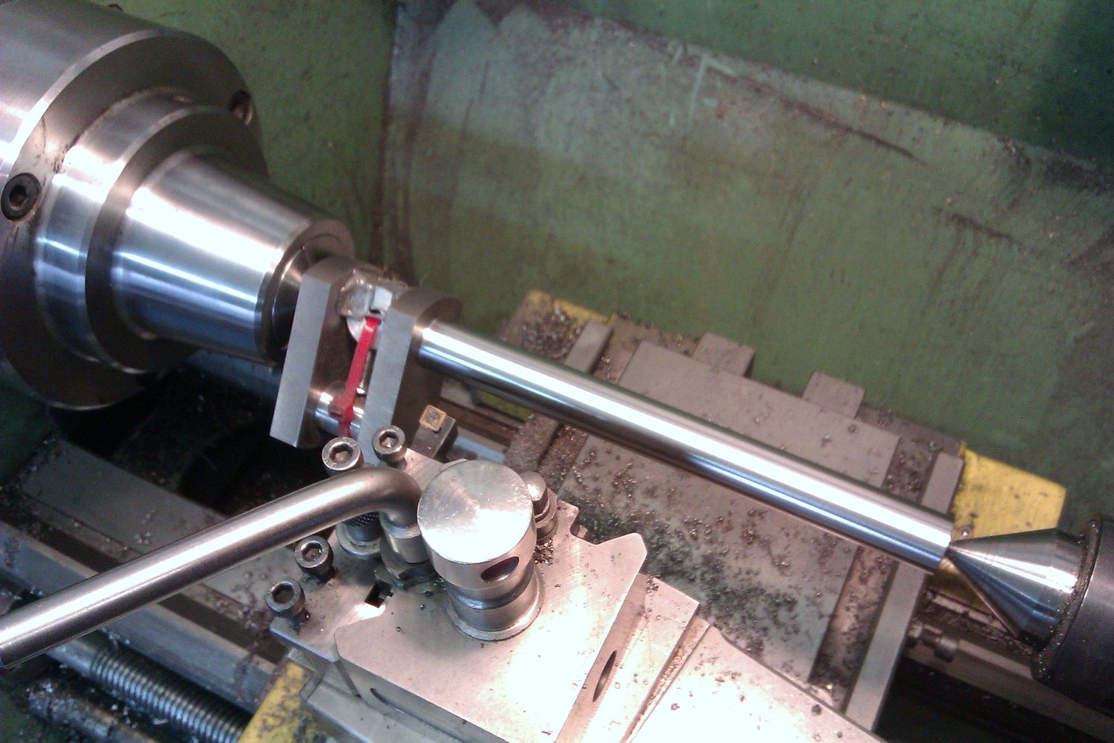
I was getting a bit of chatter on the main shafts so resorted to holding one end in a collet while I took the other down to about 0.010" ovesize and also did the outer edge of the webs. Final cuts were between ctrs with a HSS tool rather than the indexables.
With the crankshaft finished I could start to make some of the bits that fit onto it.
The pully is quite simple just a crowned outer and a 5/8" hole bored to a nice sliding fit on the shaft.
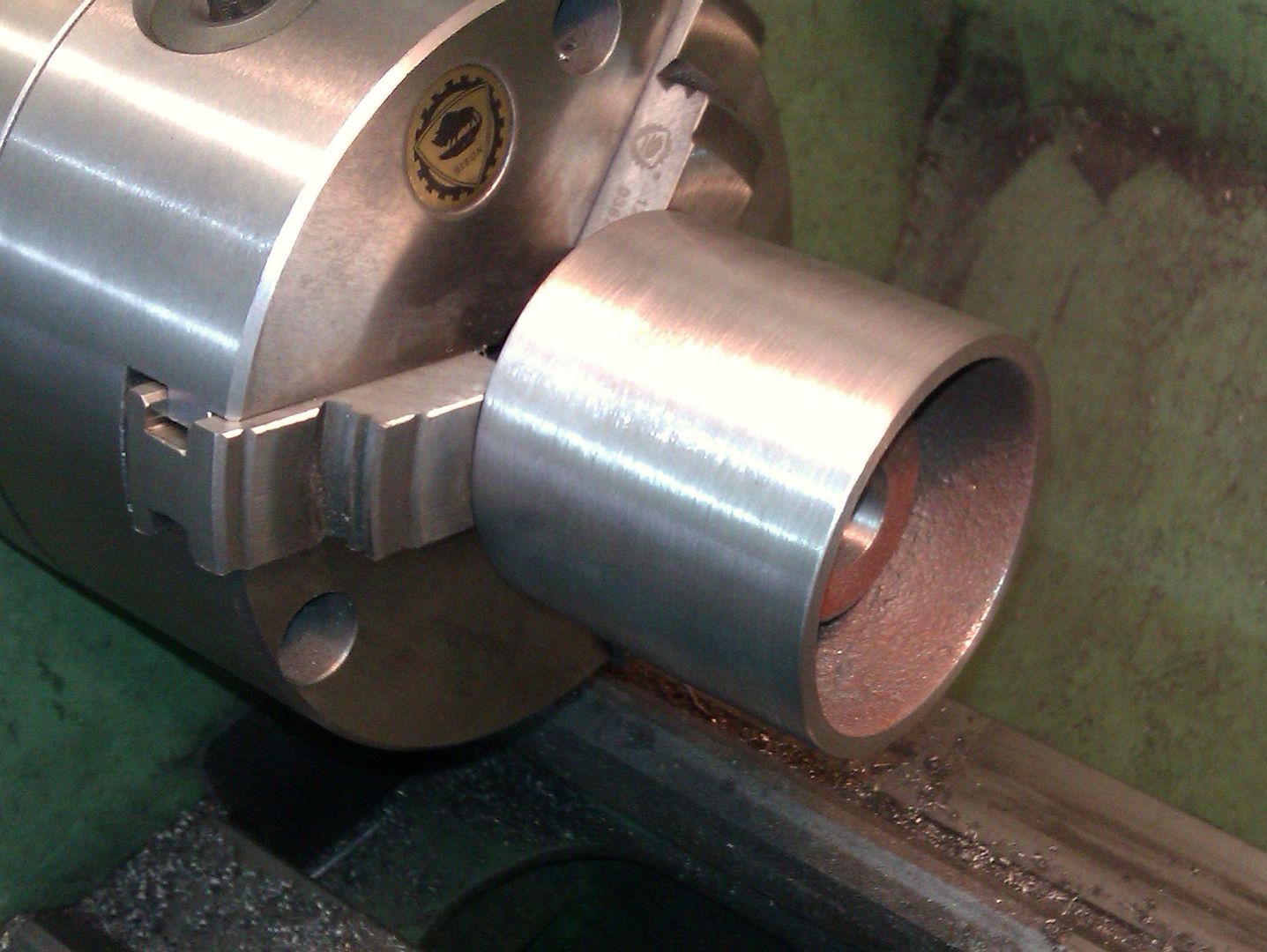
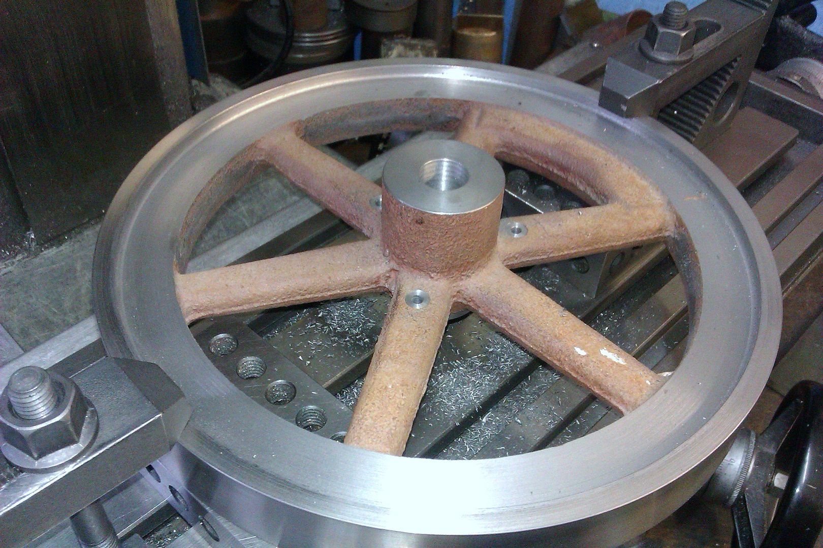
I was able to hold the flywheels in the 4-jaw and get the inner face of the rim as true as possible then turn the OD to size.
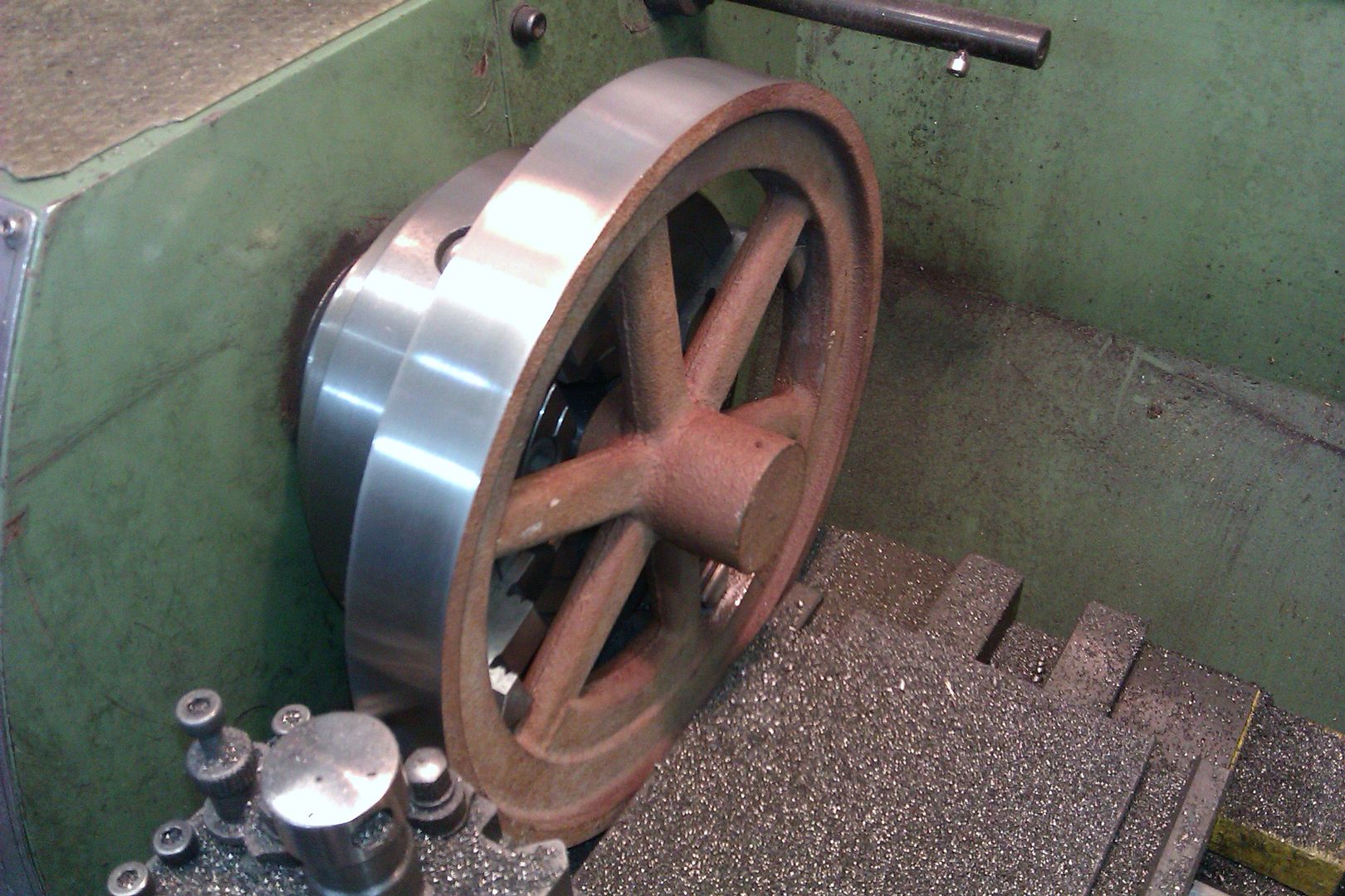
[youtube1]https://youtu.be/9rnE5jZwPR4[/youtube1]
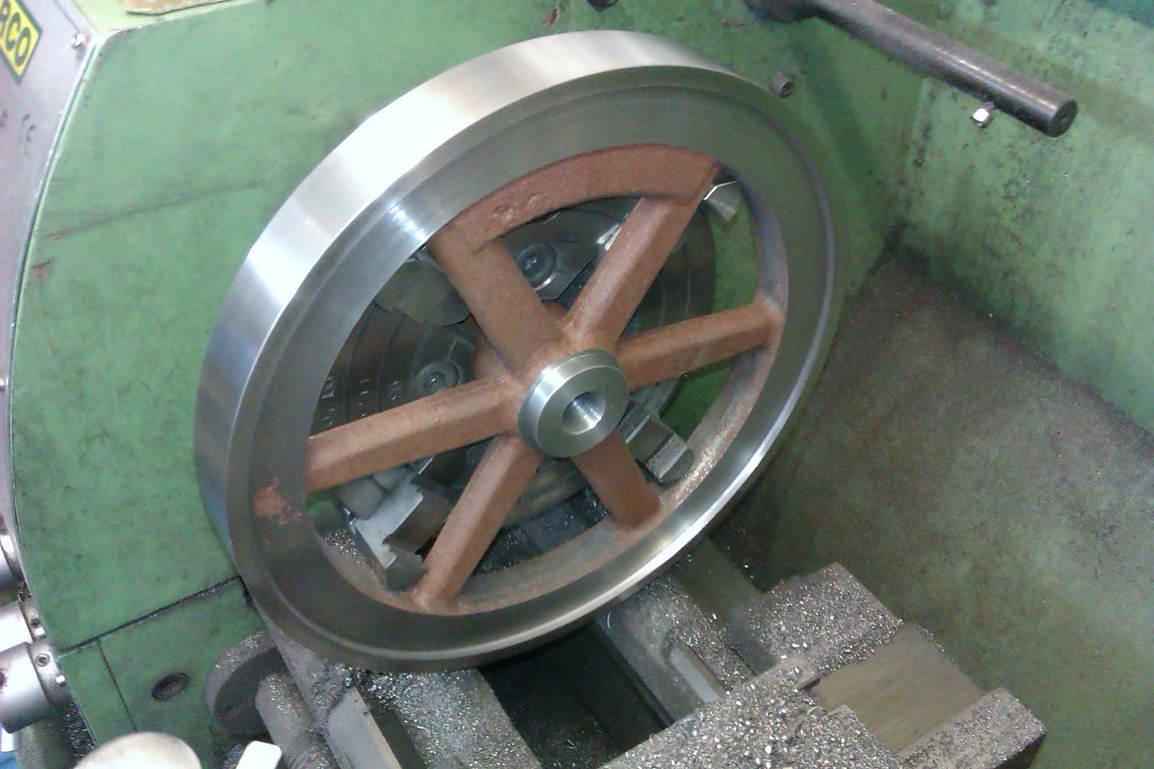
Followed by the side and then facing and boring the hub.
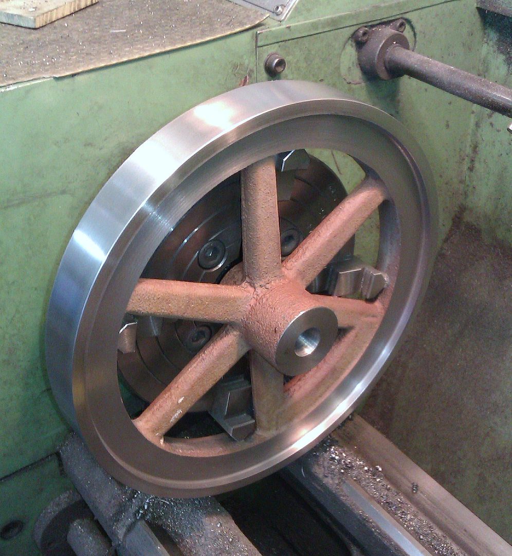
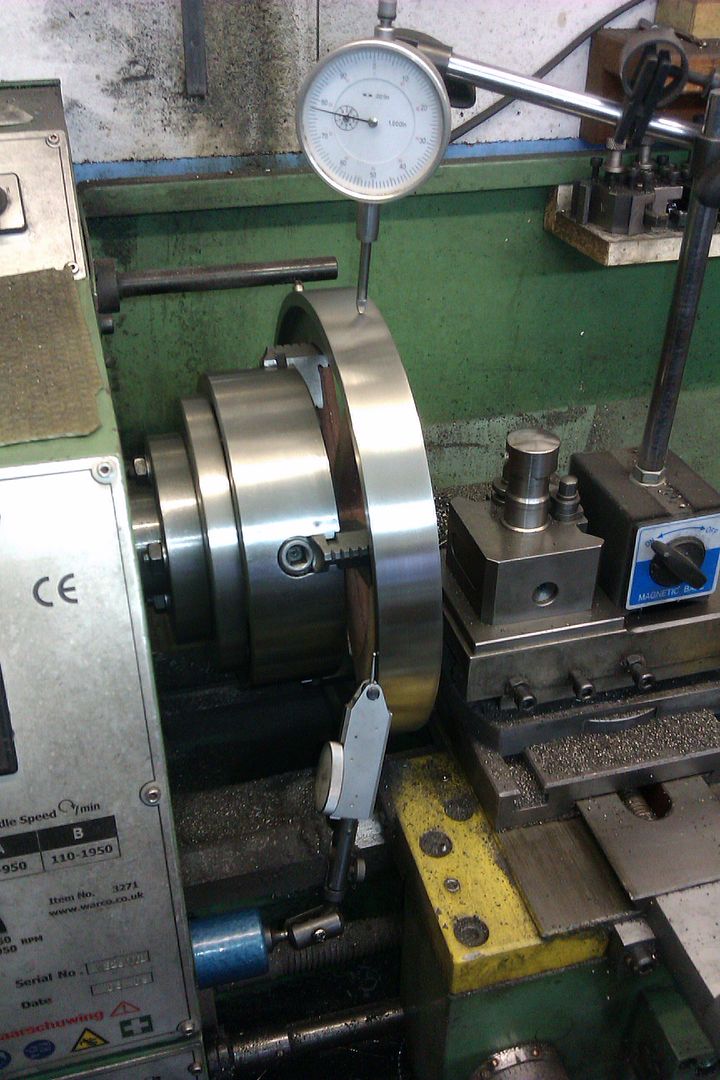
To machine the other side I use a dti on the rim and another on the back face until it was all within 1/2 a thou.
There are a couple of small areas that were a bit low but they can be filled later. This is the governor side flywheel so that also needed a register for the governor weight bracket.
Finally 3 drilled and spotfaced holes to take the bracket bolts.