The Eccentric (part 2)I was hoping to get this written earlier today, but better late than never

.
In the last post I was building the eccentric which is an Oreo cookie-like arrangement of three parts that fit together. The good stuff in the middle is a ring that will be drilled and tapped for the eccentric push rod that operates the valve. In that last post I made the ring out of brass, for the sex appeal of course, and made the simple side of bright steel. Here I make the other side which includes the eccentric offset.
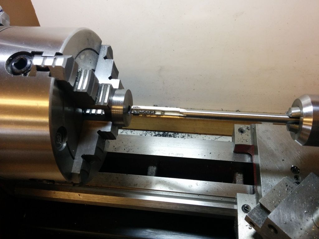
As with the other side, I started with a hunk of 1.25 inch CRS (bright) steel. This one is a bit longer as the finished part will be 15mm thick. I faced both sides roughly and then needed to chuck it with enough material exposed to turn down an 8mm section. Perhaps I should have used a longer length and parted it off, but instead I decided to give this a try. I had to space it out and keep it square so I used (literally) my square and couple parallels as reasonably accurate spacers. Of course I had the power off while getting it setup! I was a little concerned about the short grip, but I was able to really tighten it down because the other end will be turned and any marks will be long gone before I'm done.
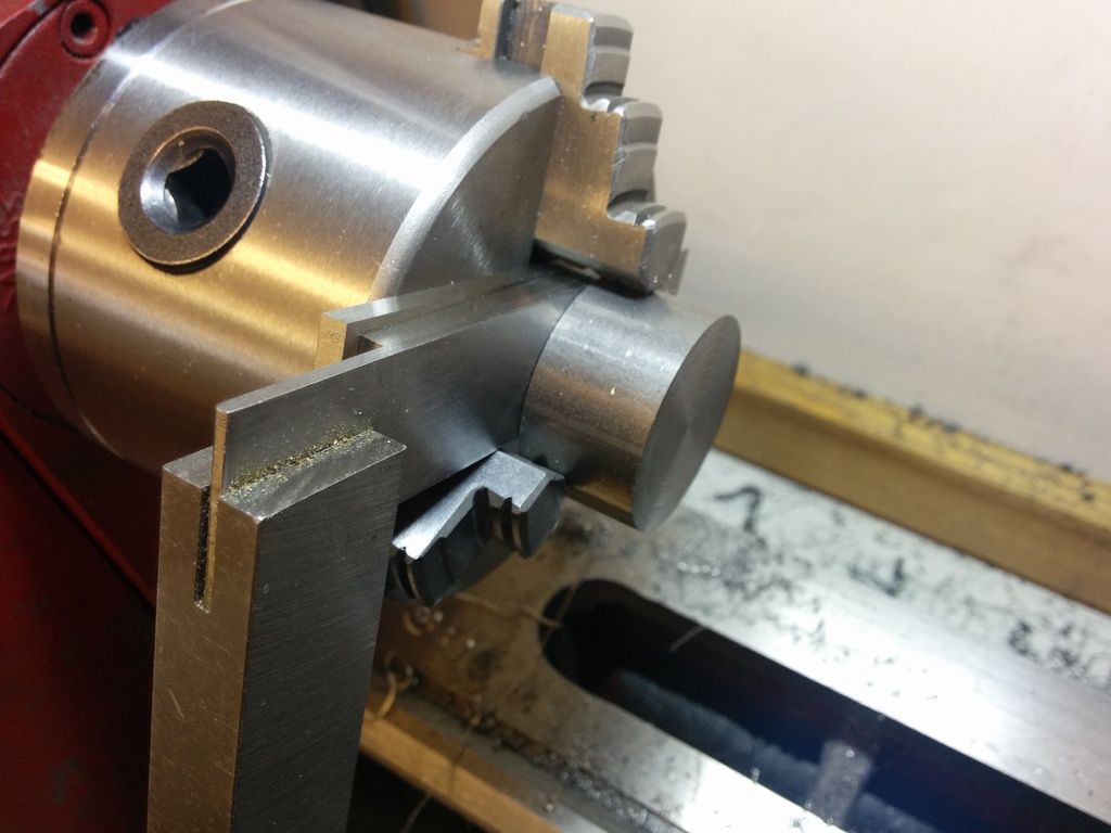
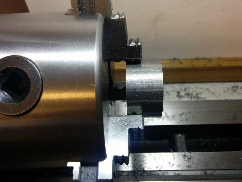
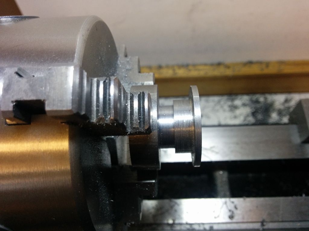
As before I turned it down, but this time was shooting for 16mm to fit the other CRS part I made earlier. I was careful not to overshoot this time. I stopped as it got real close to fitting (the second photo).
Now I had to go real slow. I followed a process I've used a few times on this engine. First turn a portion of the length down an extra thousandth and test for a fit. If it didn't fit, I'd finish the pass and repeat. Eventually the other part fits the portion and I know the rest (about 2/3rd of the length) is one thousandth over. Unlike the brass ring which was ok to be a sloppy slip fit, I really wanted this part to be a press fit with the other part. Worse case if I screwed up I could glue it up with loctite, but my goal was to press. And I didn't want to press too thick a fit because the material needs to go somewhere and I didn't want the brass ring, which fits between these two parts, to seize up in the space. So it was careful work here.
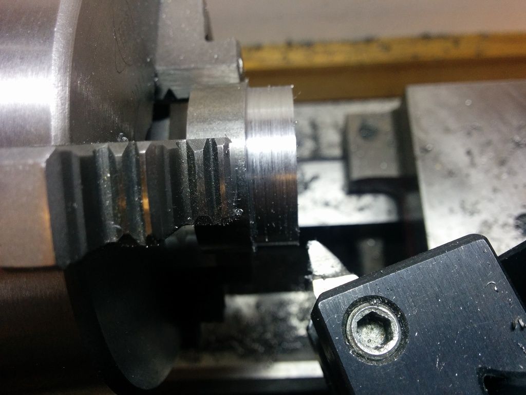
As I've often done on this engine, I finished up the shoulder with my parting tool. It was ok to run a little extra deep because the inside of this part won't be seen. I probably should grind an HSS cutter for this work...but the parting tool worked ok.
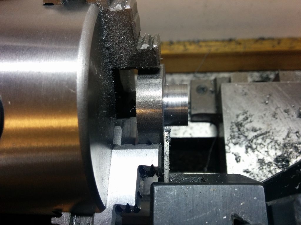
Looking A-OK. But I can't press it now, of course.
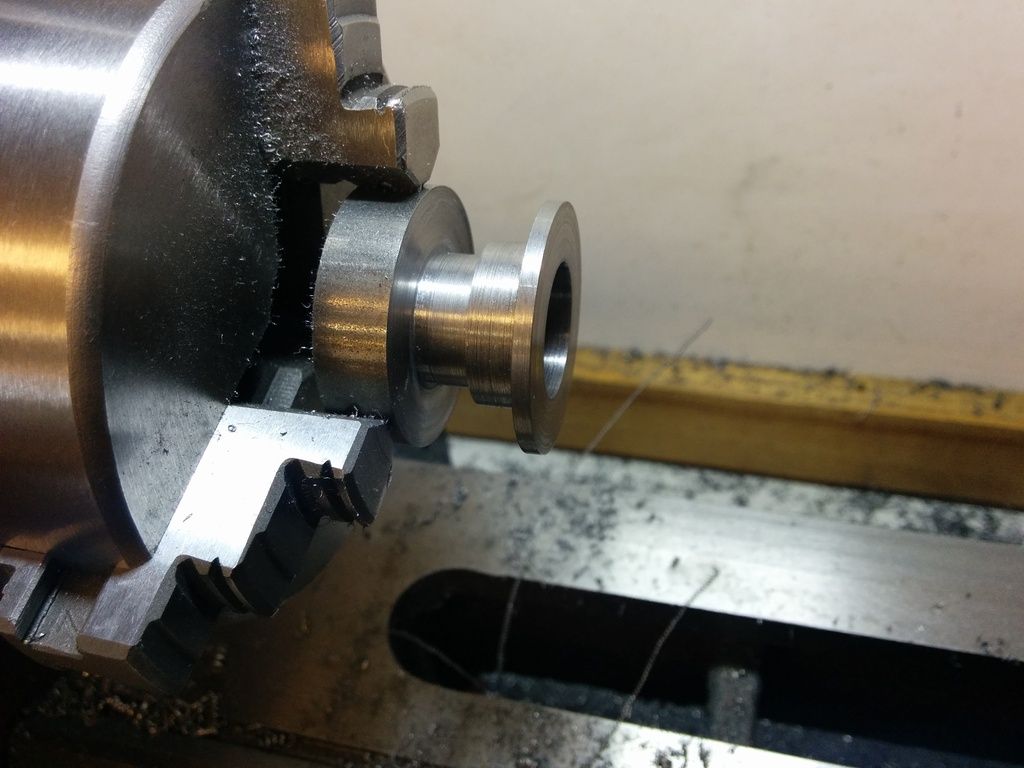
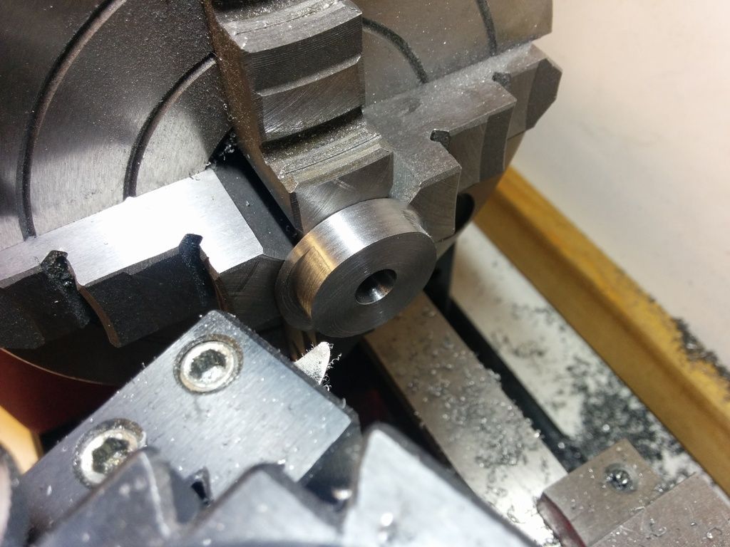
Now I flipped it around to do the eccentric part. The first step, though, is to turn the diameter to 30mm to match the other half of the Oreo cookie. We wouldn't want the sides to mismatch, would we? I used my 3-jaw for this since there is no offset, and of course the 3-jaw chuck was already in the lathe.
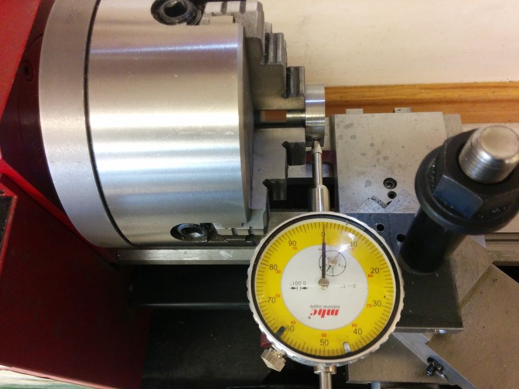
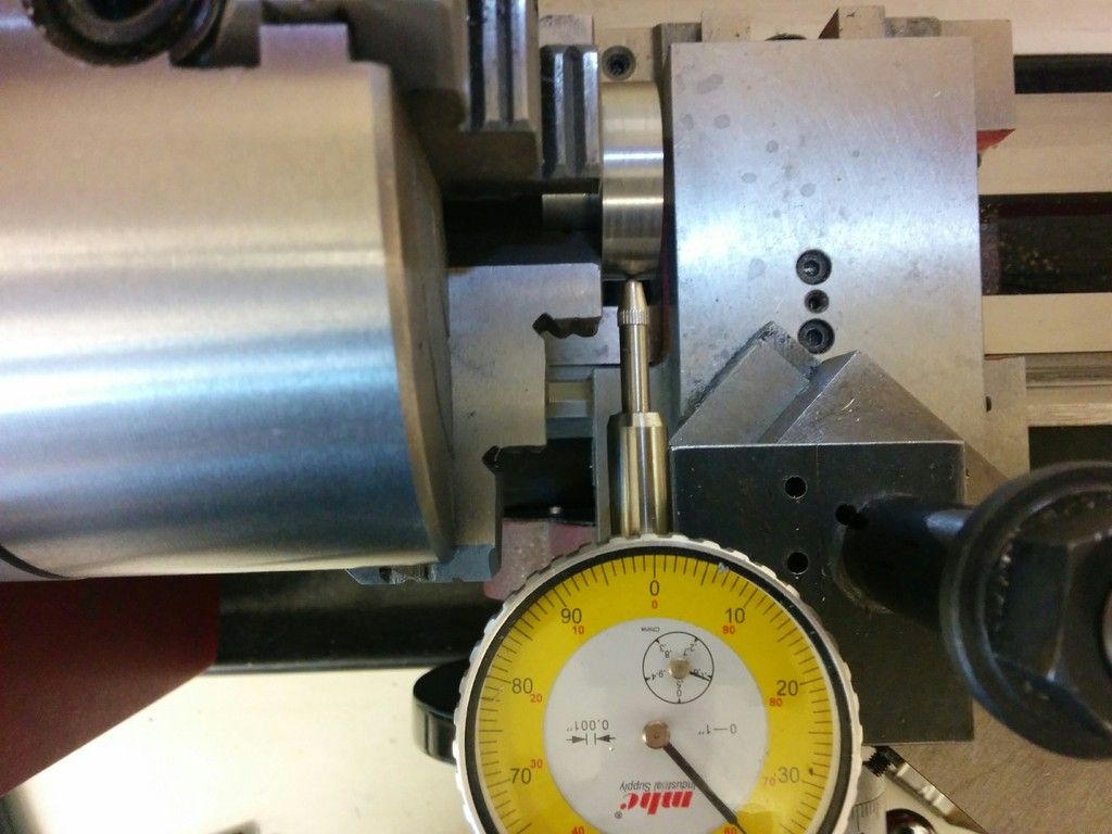
It's time for the eccentric turning and I had to switch to my 4-jaw chuck. It's a 5 inch chuck and a little big for this lathe, but working good so far. I centered it first, and then I pushed it for a 3.5mm offset. That's 138 thousandths of an inch, so my dial indicator ended up at a full turn and 38 thousandths extra (second photo).
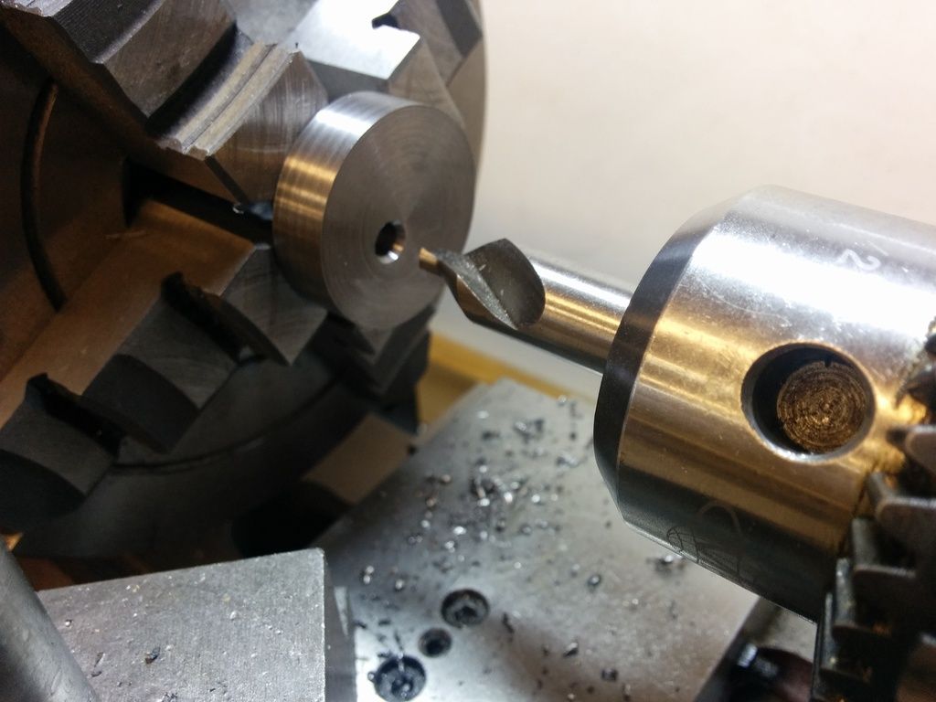
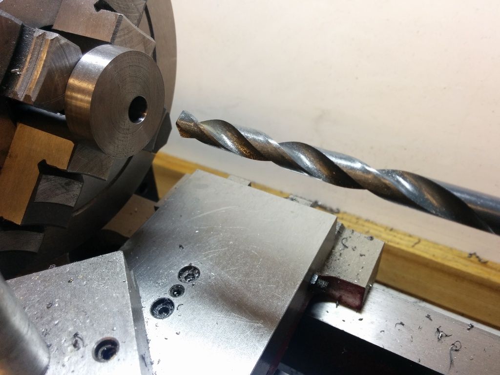
Next I drilled for the 5/16 inch shaft I'm using. I thought drilling was best as a start so I can easily see it was offset the way it should be. The shaft actually measures at about 0.306 rather than 0.313, so I drilled to an N bit and then reamed it to 0.3115. I figured it wouldn't hurt to be closer in diameter because the 5/16 inch drill bit will probably go oversize. I'm sure drilling would have been fine. This was a "what the heck" thing:).
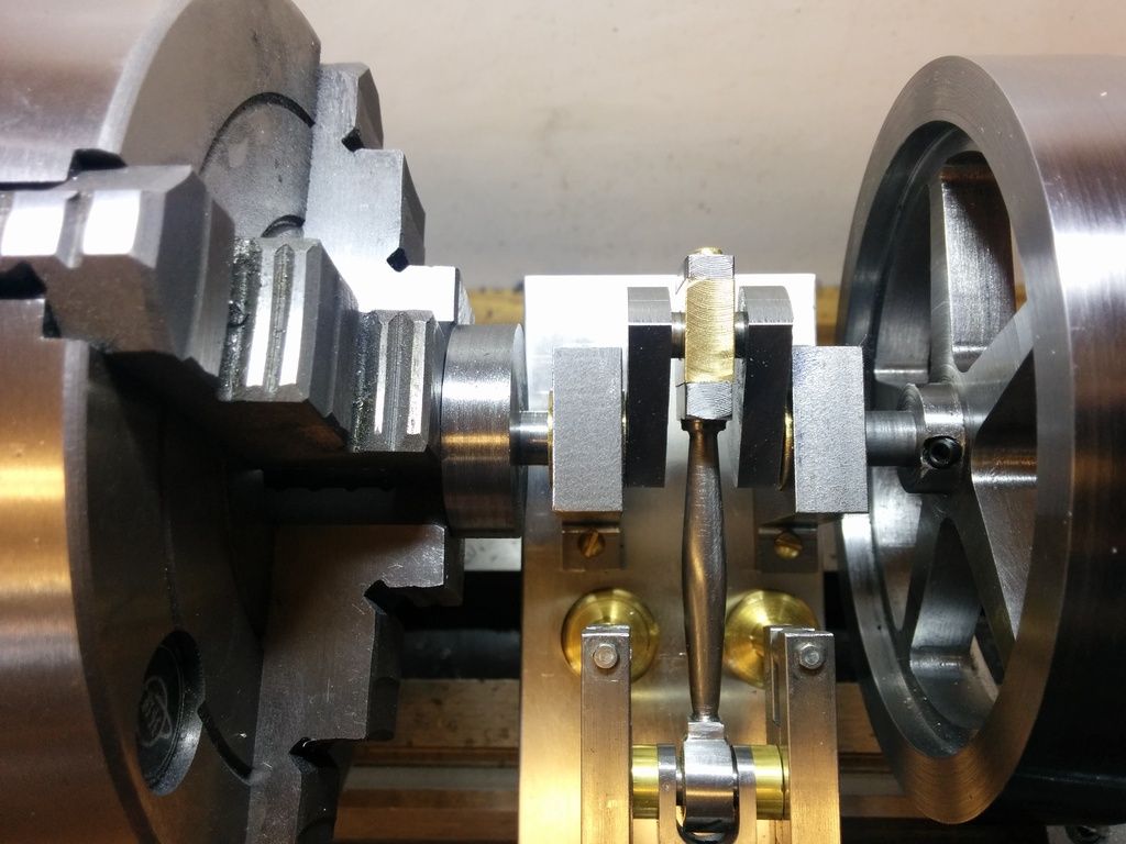
And now I could check the fit using the engine itself. Power is off of course.
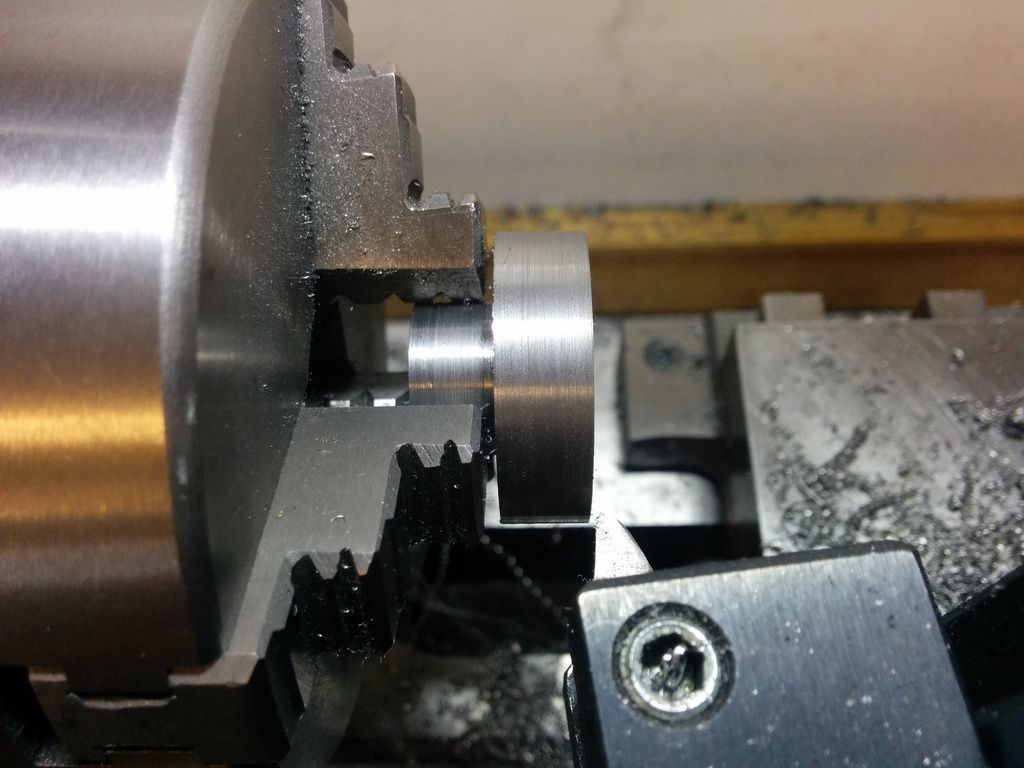
Now I started turning down the outer edge. It was already located correctly so this was just a matter of dealing with an intermittent cut until I got down to 16mm, which was a fairly arbitrary measurement anyway. That is, it looks nice.
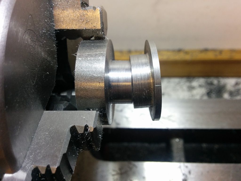
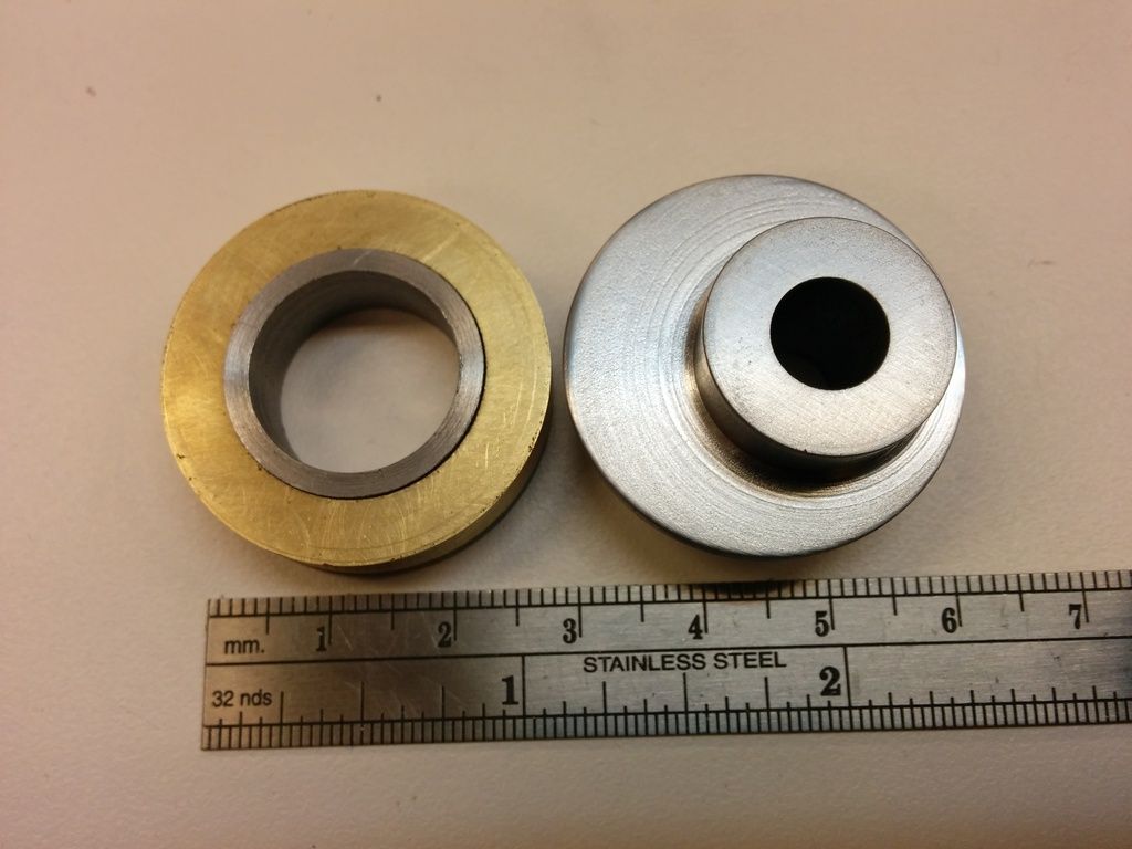
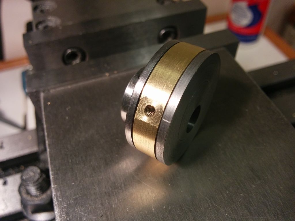
And here are the three parts now. The new one on the right should press fit inside the one on the left.
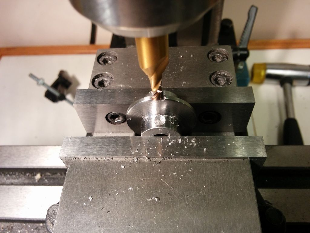
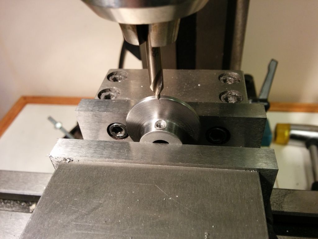
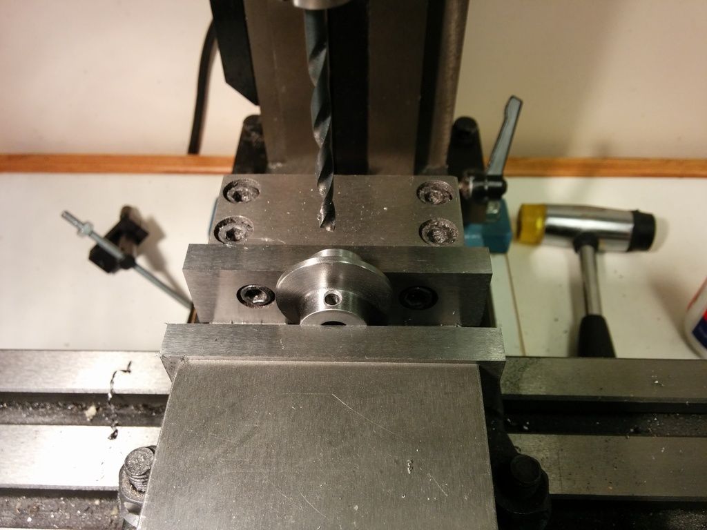
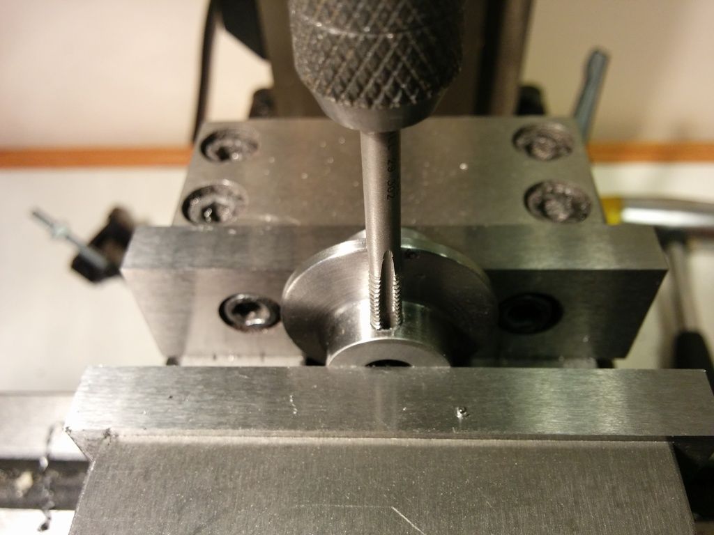
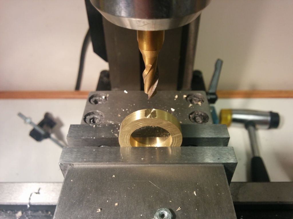
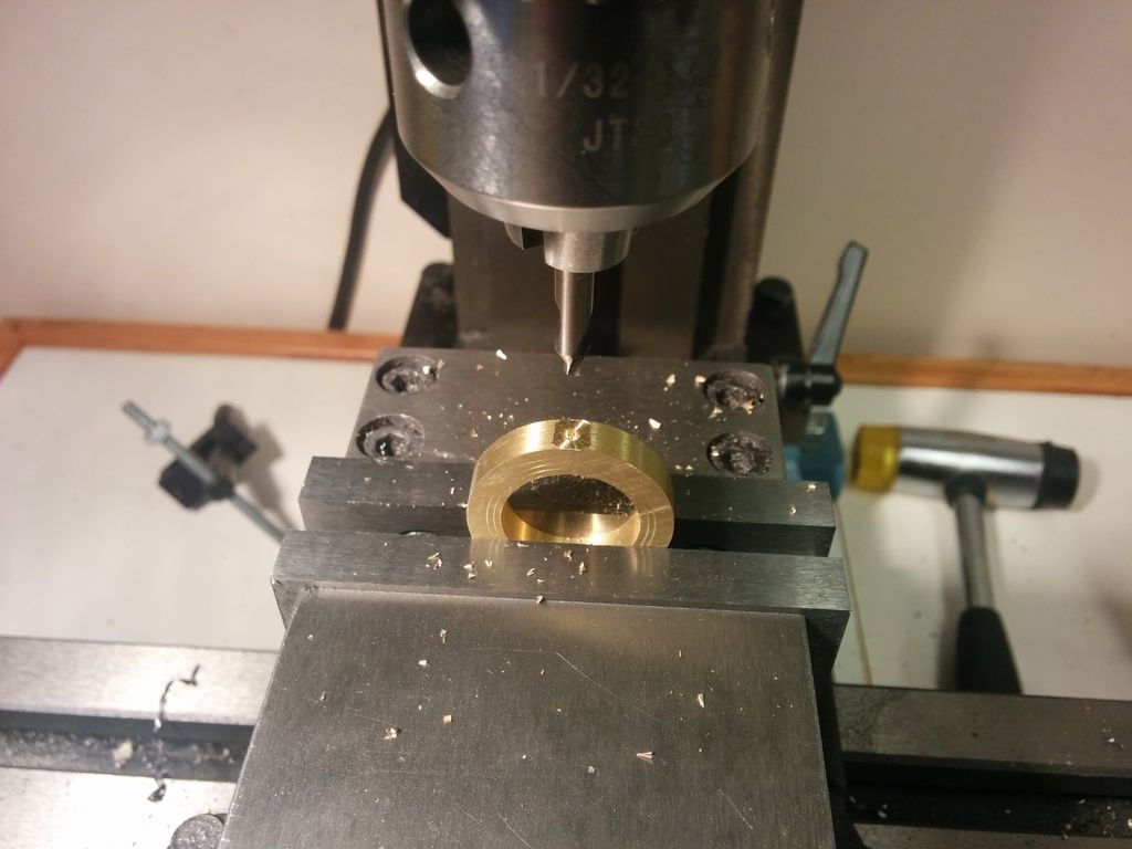
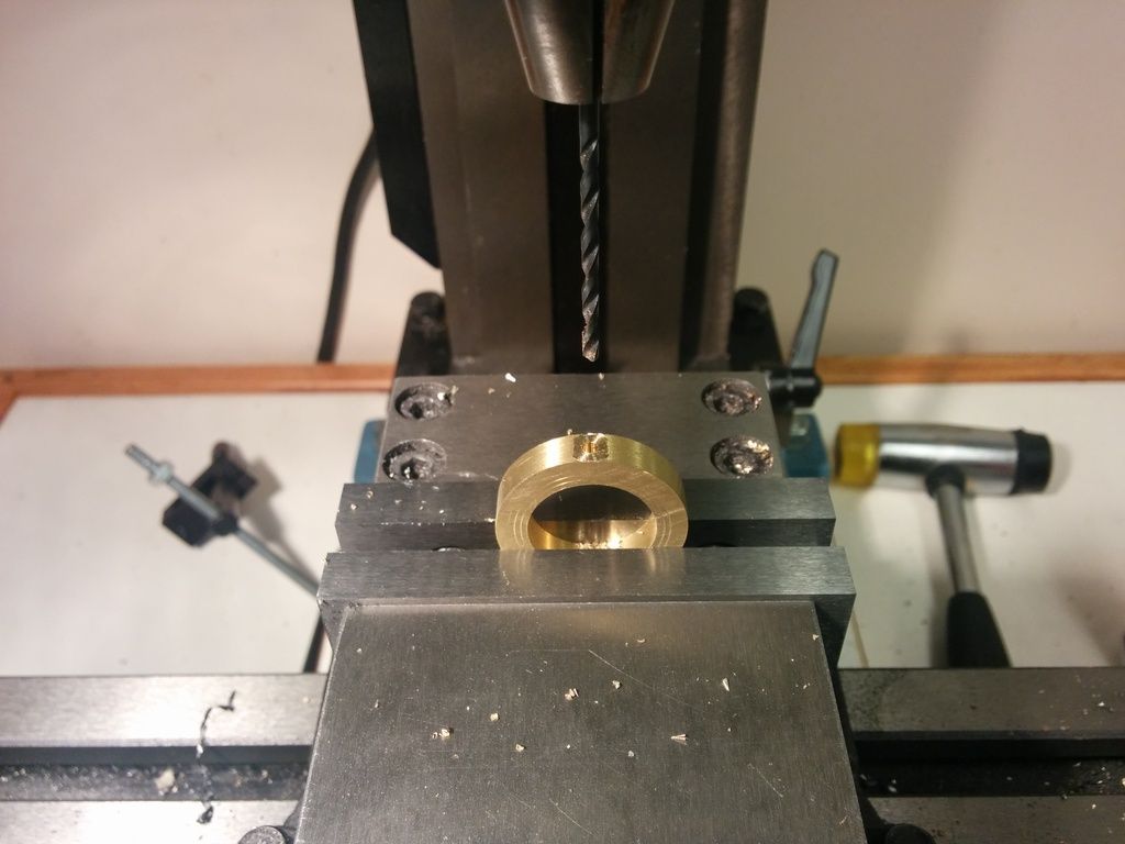
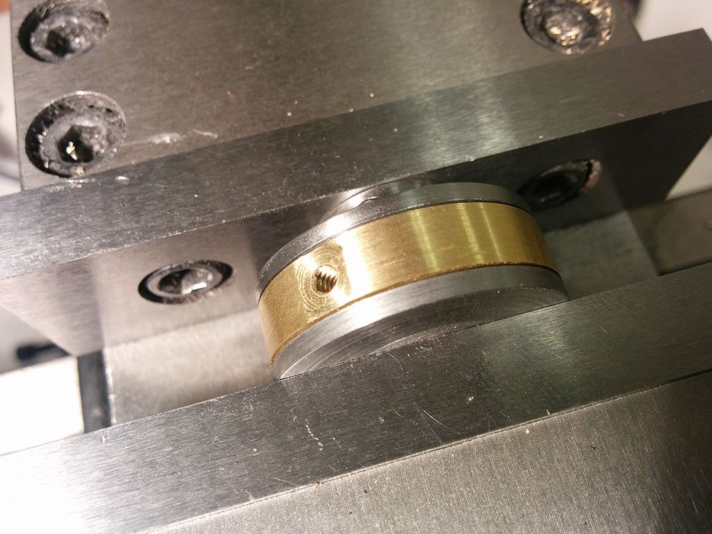
The new part needs a set screw to clamp onto the shaft. I used a 3/16 inch end mill to make a flat, then drilled and tapped as shown in these photos. I had to use an undersized starter drill to avoid running into the side of the part. I tapped it using an 8-32 set screw to match the flywheel.
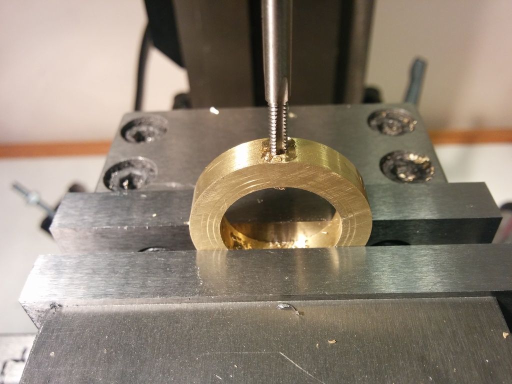
Before pressing the assembly together, I needed to drill and tap the brass ring to accept the eccentric rod which I haven't created yet. I decided to go with a 4-40 thread, even though 5-40 would be better. I don't have 5-40 taps and dies yet. They don't seem to be very common, though I do plan to buy a set soon. I plan to use a 1/8 inch rod which would be a perfect fit for a #5. But 4-40 should work fine.
Now for the big moment. It's time to press the assembly together. I used my mill vise and as I turned the vise crank I kept spinning the brass ring around to make sure it stayed loose. It did. If it hadn't, my plan was to stop quickly and pull it apart before I was at the point of no return. Well, that was the plan...no proof it would work.
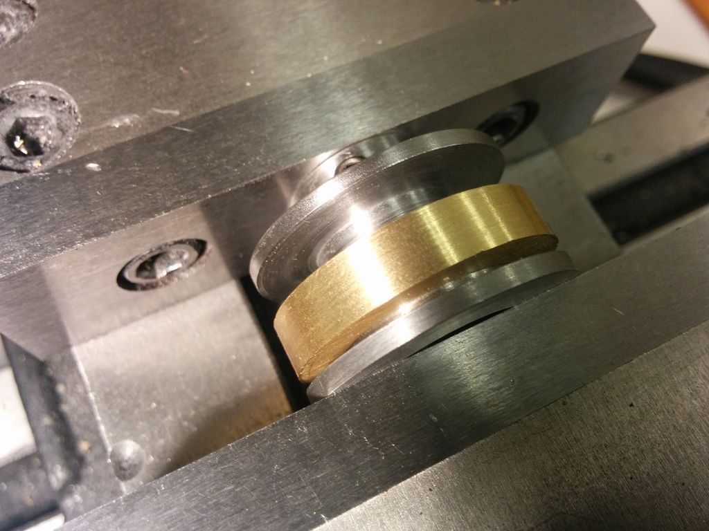
Perhaps I should have made the spacing between the outsides a little tighter, but I didn't want to trap the brass ring too tight. And I really think the brass make it look nice.
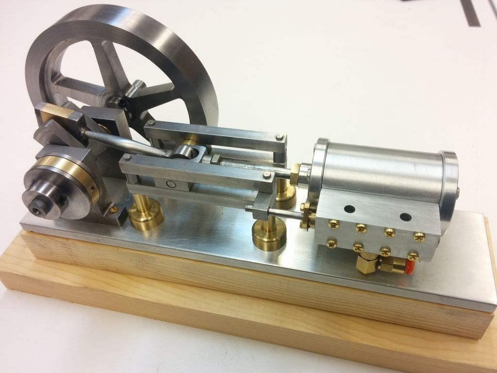
And here it is installed on the engine. This baby is wanting to run pretty soon now!
My apologies for the volume of pictures, but I know you guys like to see them, and I thought it's good once in a while to show I really do go through all the steps with starter drills, drilling, tapping, etc. This build log is for the beginners out there after all.
Todd


