Heres another pic of the die components.
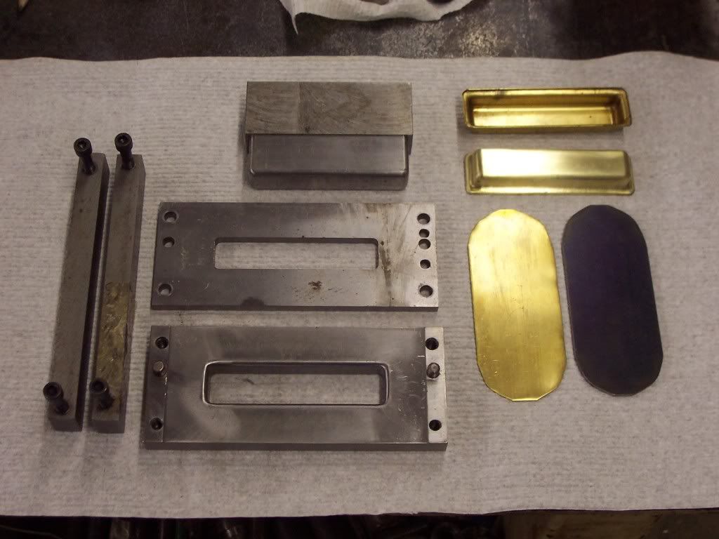
The die is at the bottom. The stripper is above it and the punch is at the top. The bars on the left are for support of the stripper. The cavity in the die determines the size of the tank body and was arbitrary, the stock size I had was the limiting figure in the design.
The die cavity was milled to size and then the draw radii were milled with a corner cutter. To provide for tangencies at the junctures of the surfaces I measured the small dia of the corner cutter which dictated what size endmill to use to cut the cavity leaving the correct radius that would match the radius of the corner cutter. The corner cutter radius is determined by the stock thickness. The draw radius should be 4 - 10 times the stock thickness. I used .02" thick stock so I went with a .125" corner cutter which will give me a radius to stock ratio of a little over 6:1.
Once the radii were milled they were polished smooth with sand paper. The die was made from 4140 RC 28-30. The stock will need to flow around these radii so they must be very smooth with no imperfections. Normally the die would be made from A-2 or another tool steel and be hardened to RC 62 but for a few pieces this worked just fine.
The stripper was dowel pinned to the die for alignment and then the slot for the punch was milled to size. A clearance of .001" was used all around. The stripper and die should be milled in the same setup to make sure the slots line up perfectly.
The punch size was determined by the die minus stock thickness minus .001" clearance all around. A corner cutter was used to make the radii just as the die was. The radii were now polished.
The first pic shows the brass stock blank placed on the die. It was positioned by hand and then then stripper is placed over the die.
I found that the stripper was lifting up when in use so a couple of support bars were placed over the stripper for added strength.


