Author Topic: Pumped Up Cameron Steam Pump  (Read 39431 times)

Offline sbwhart

  • Full Member
  • ****
  • Posts: 745
  • Live Long and Prosper
Re: Pumped Up Cameron Steam Pump
« Reply #15 on: December 28, 2014, 06:45:12 AM »
Great work Jason  :ThumbsUp: :ThumbsUp:

I'll be following along with great interest.

Stew
A little bit of clearance never got in the way

Offline Alan Haisley

  • Full Member
  • ****
  • Posts: 693
  • Fuquay-Varina, North Carolina, USA
Re: Pumped Up Cameron Steam Pump
« Reply #16 on: December 29, 2014, 01:13:43 AM »
The fabrication may turn out better than a casting would. It's really looking nice.

Alan

Offline Jasonb

  • Full Member
  • *****
  • Posts: 9490
  • Surrey, UK
Re: Pumped Up Cameron Steam Pump
« Reply #17 on: January 01, 2015, 07:15:43 PM »
Thanks for all the kind comments

The next logical part to make was the top plate(s) for the columns, I decided to keep these as one piece for now as that would help keep the tops of the columns the same distance apart as the bottoms. Some 5/16" x 1.5" bright bar was milled to length, holes drilled for the location spigots left on the column tops and then some construction screw holes added (4 per column)

I also milled some shallow slots to locate the stiffening webs and screw holes to keep the webs in place. The last 4 holes are the ones for the cylinder base hold down studs.


The column centres were found and the DRO's PCD function used to locate the M3 fixing holes


And a quick test fit of some of the screws, the heads will later be hidden with filler.


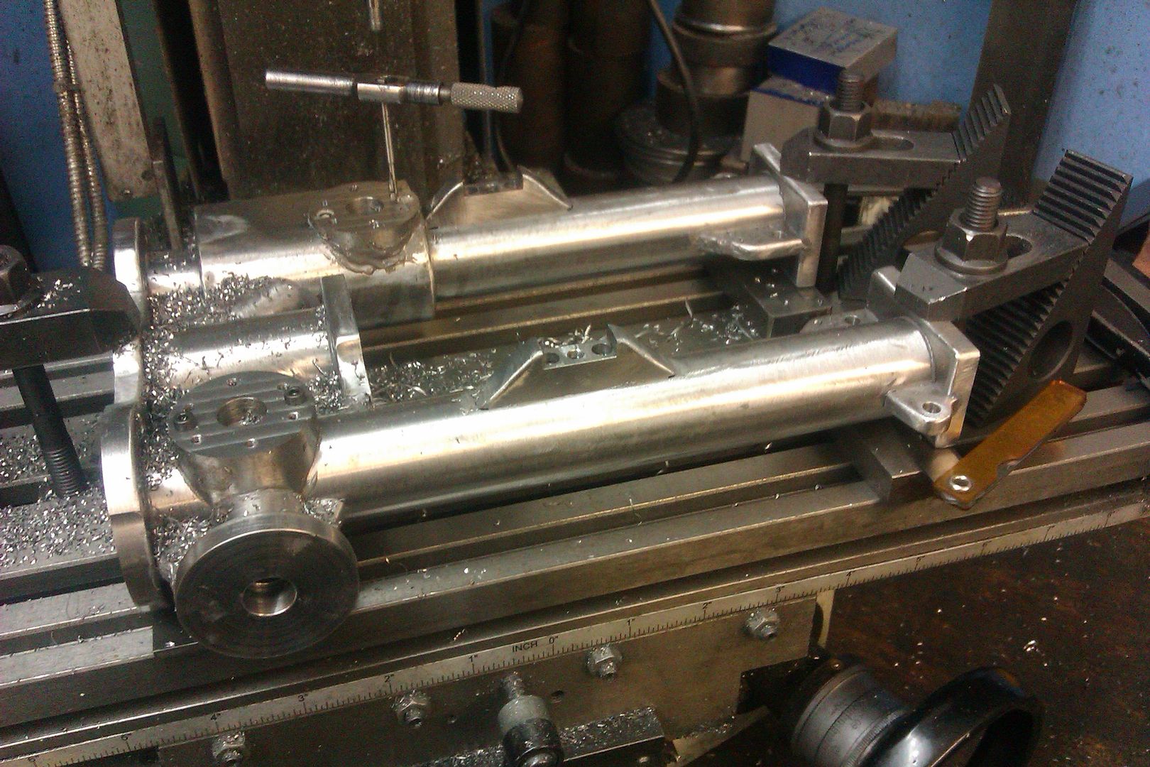
Next some similar sized slots were milled into the columns to locate the sides of the stiffening webs and also some wider ones for the bearing supports.


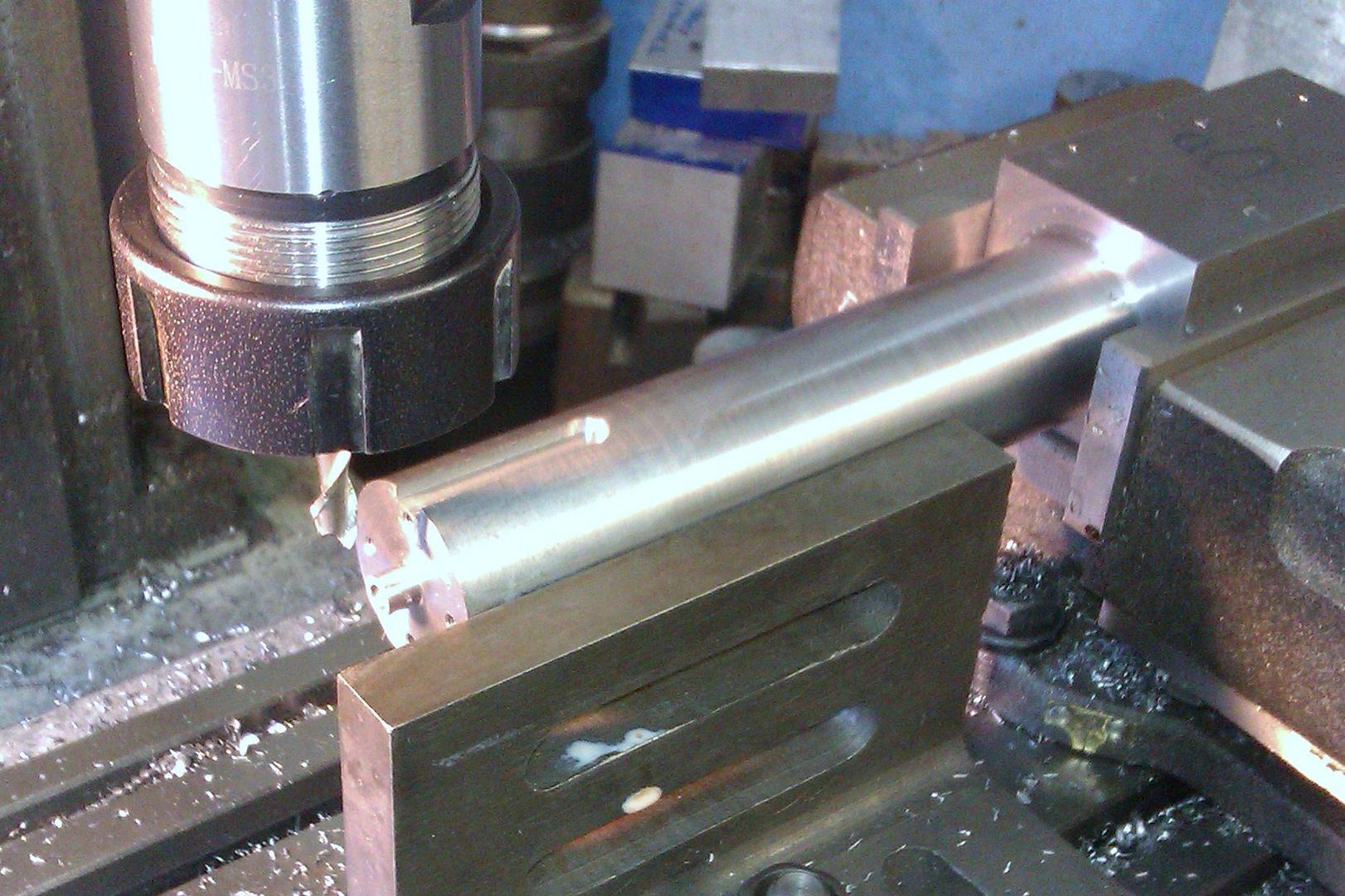
The webs and bearing supports were just milled and filed from 1/4" and 5/16" material respectively and then drilled/tapped as required. The two notches in the bearing supports are undersize and will be machined true once the whole thing has been JB Welded. Same goes for the flange faces, its a bit like leaving a machining allowance on a casting. It does not show too well on the photos but the upper 1/3rd of the columns a now have been slightly tapered.


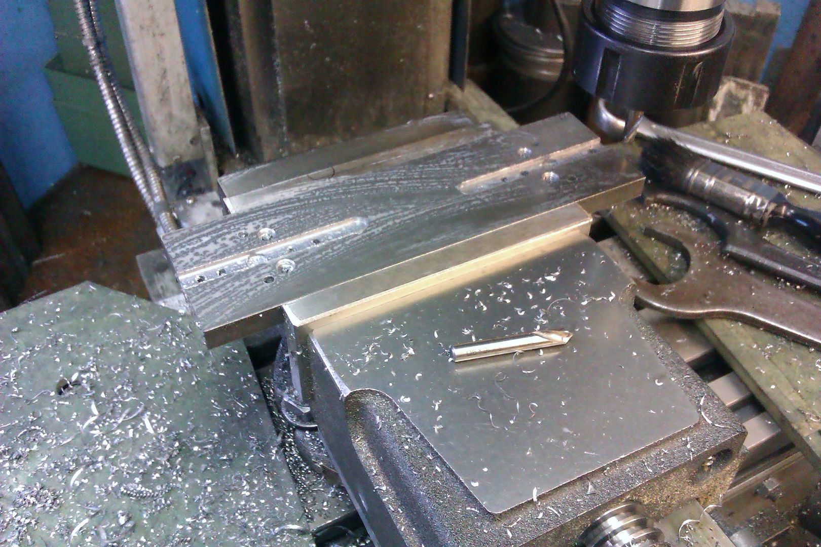
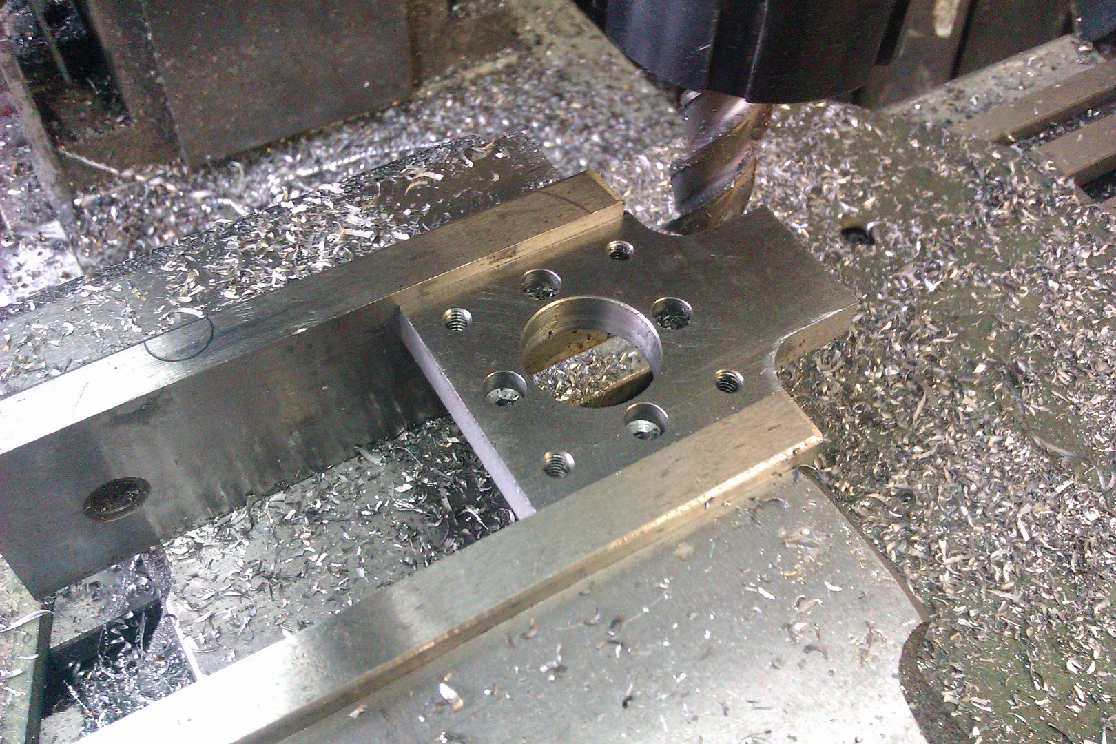
The top flange of the pump chamber is a fairly straight forward milling and drilling job, 4 construction holes, 4 stud holes for the gland and a large bored hole for the ram.


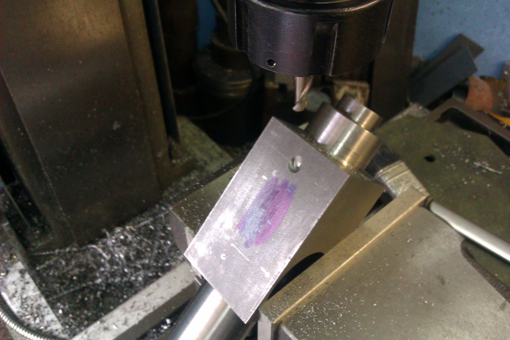
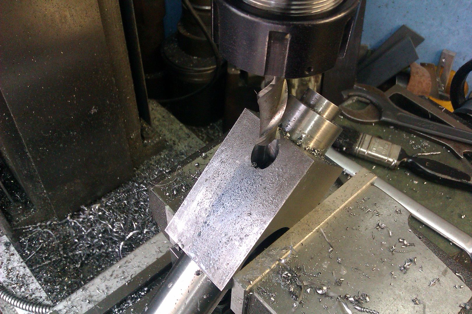
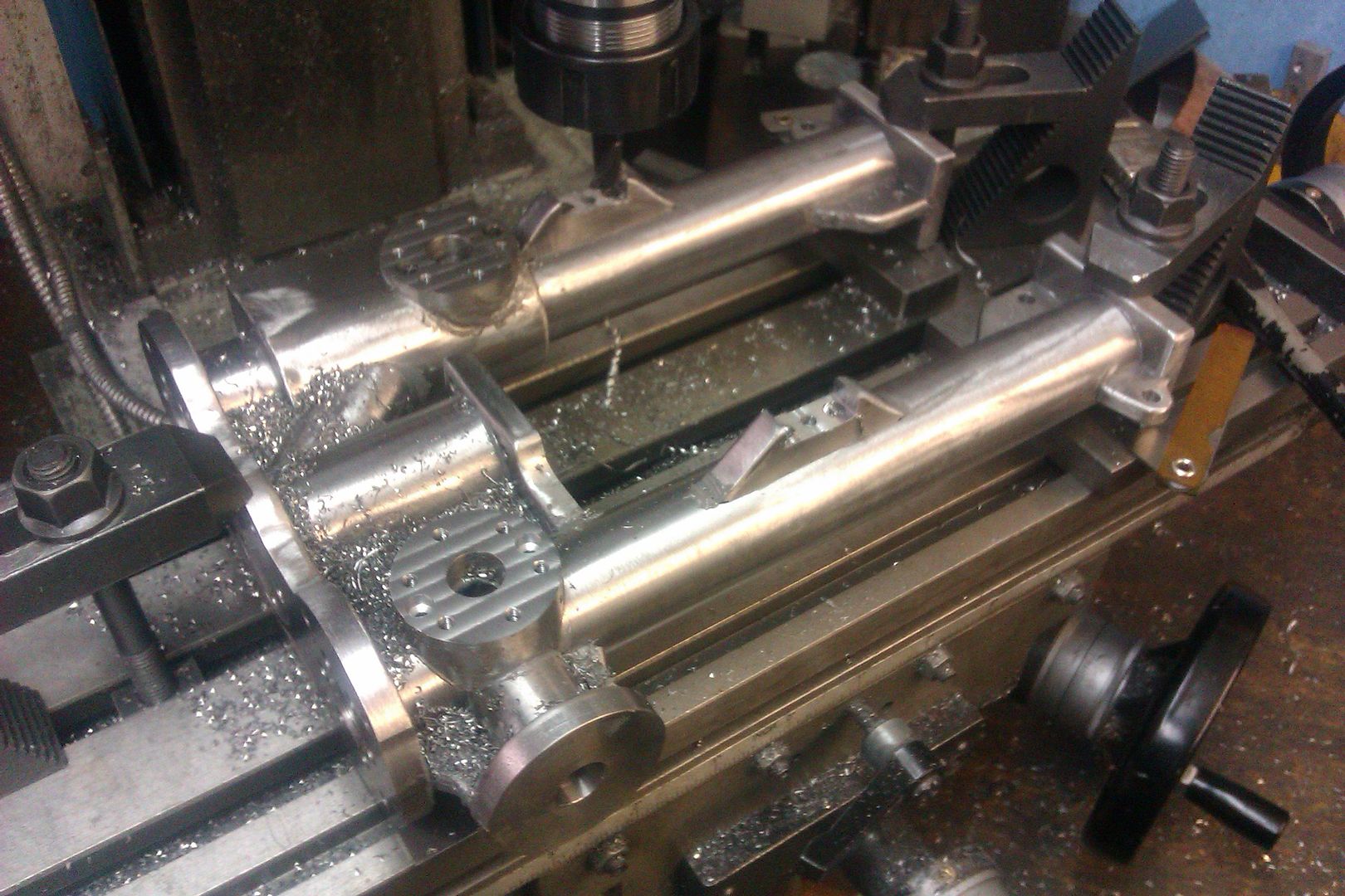
There is an angled passage that links the valve chamber to the pump chamber I started this angled cut on the column with a bull nosed milling cutter and then drilled a pilot hole 1/4" dia. This hole was then englarged with 3/8" slot drill then a 1/2" one. I had to mount the vice on packers so that the column did not hit the mill table.


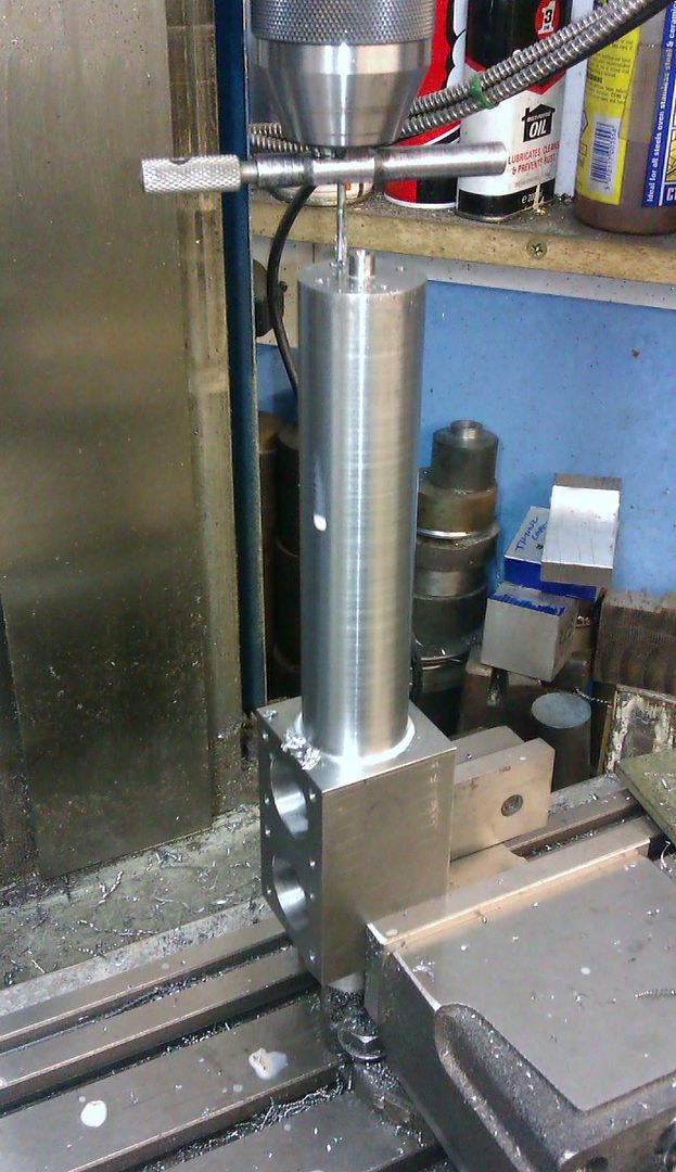
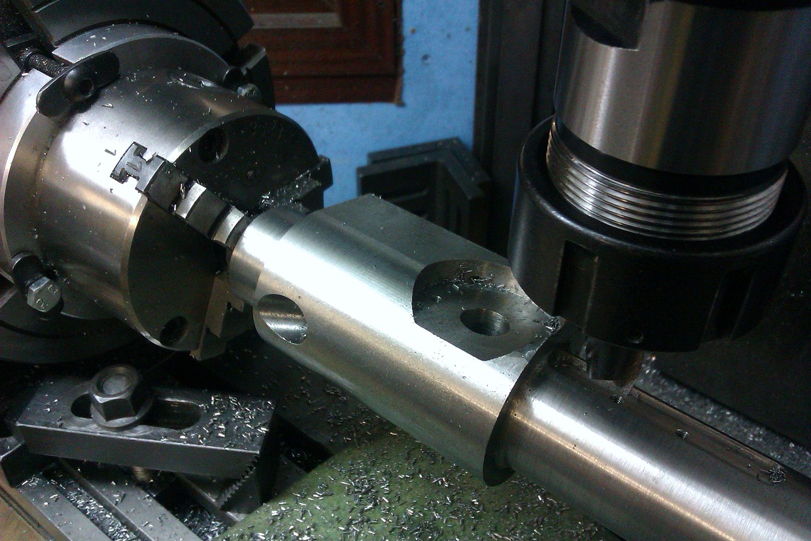
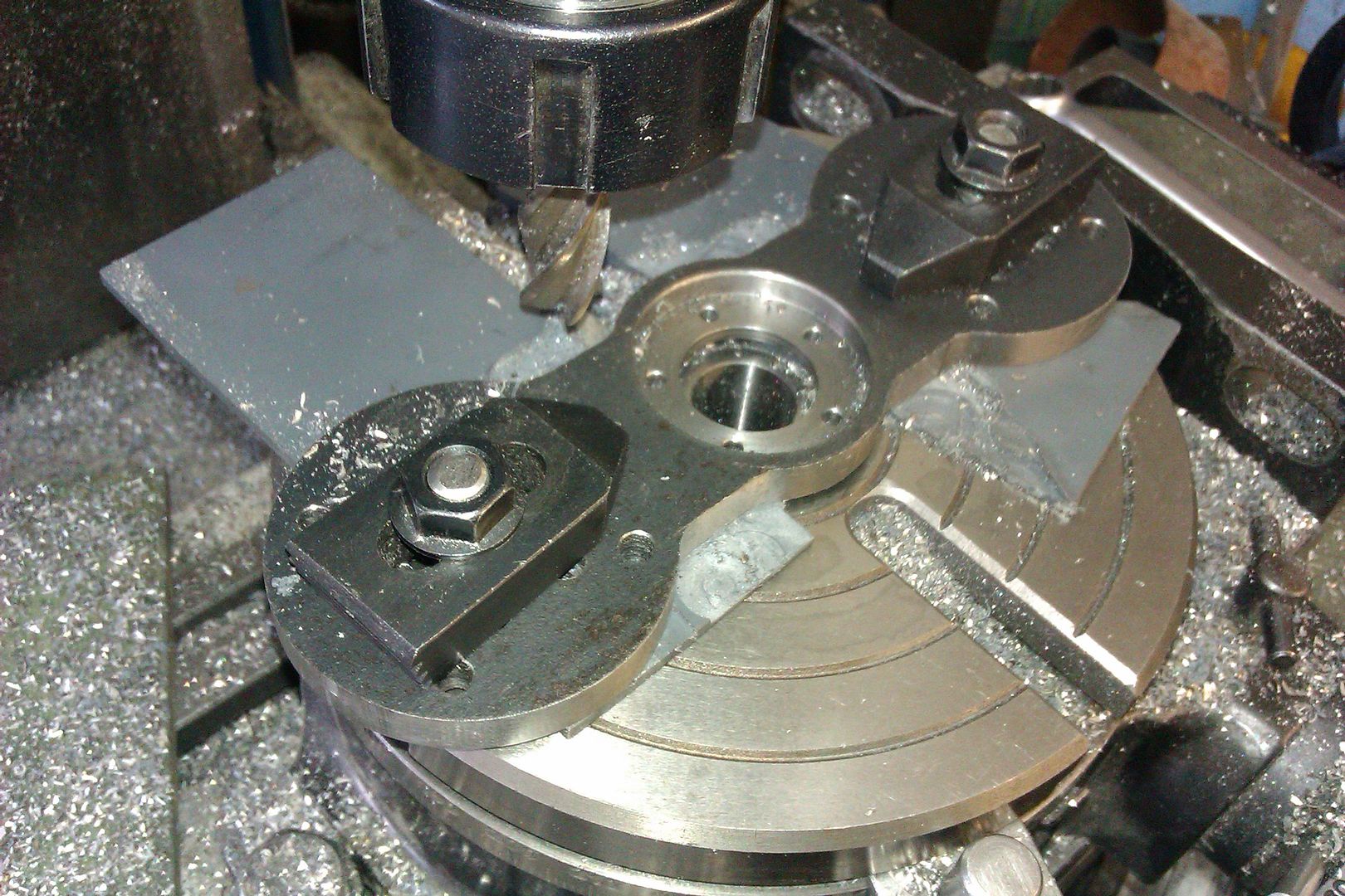
With that hole out the way I could start shaping the valve chamber from the original square section to a "D" shape. To do this I set the column up on the rotary table with tailstock support, roughed it out and then made 180 passes of 1 degree each along its length climb cutting one way, traditional cut the other to save having to crank the table back each time. Quite pleased with the finish which is straight off the tool in the photo. I tried out a sample of a new range of cutters that one of the ME suppliers sent me to test, should be available soon, they are quite nice and so should the price be too :)


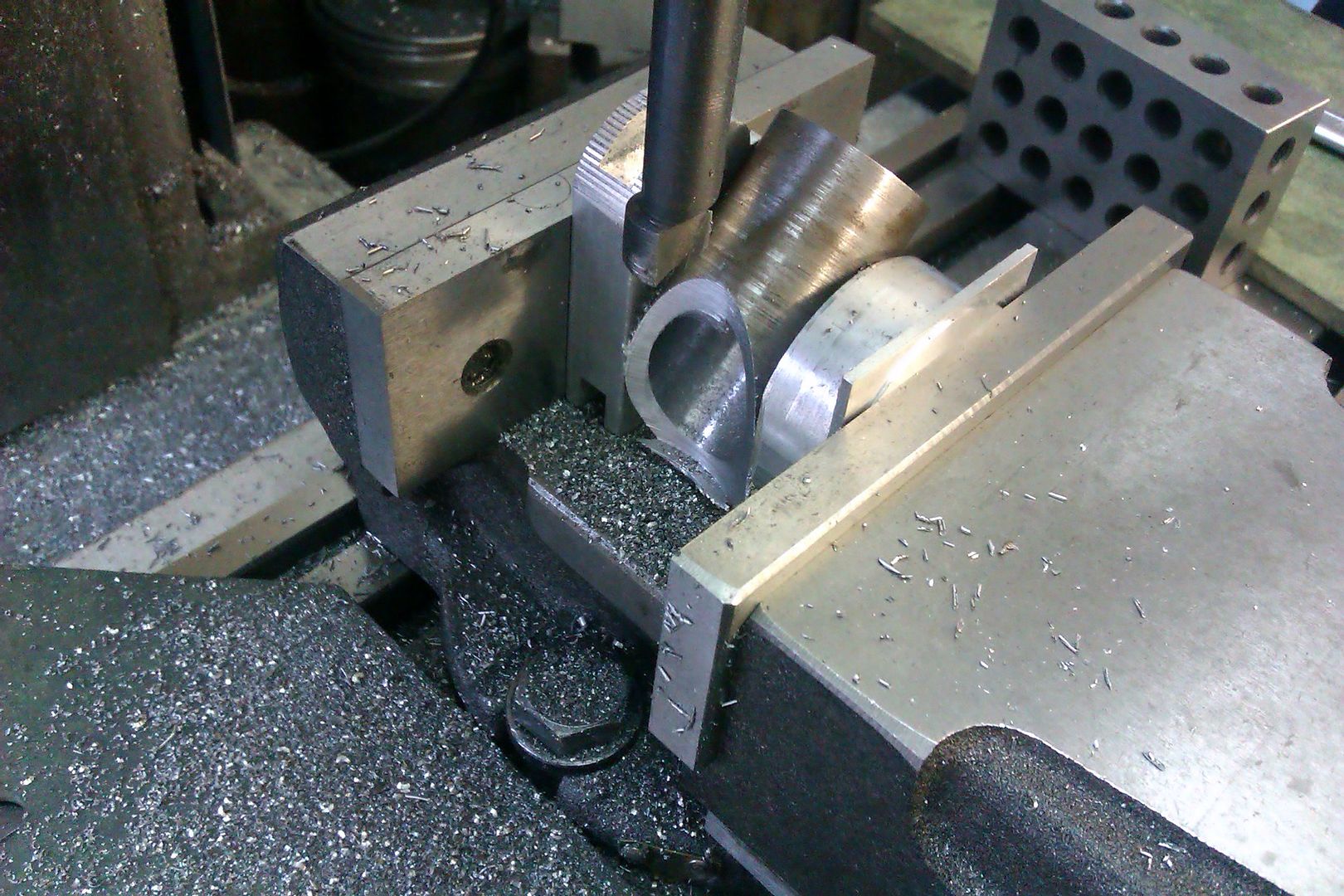
I don't think I took any photos of the pump chamber but is nothing special. Though once it was made I could get the correct radii and distance apart of the two curved surfaces that the diagonal passage has to fit between and use a boring head to cut them. The work is held between two scraps of aluminium so both curves can be cut at the same setting without worrying the cutter will hit the vice as the dia of the cuts are larger than the work piece.


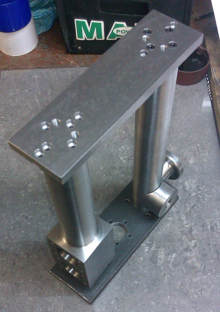
Add a few more webs and its almost there.


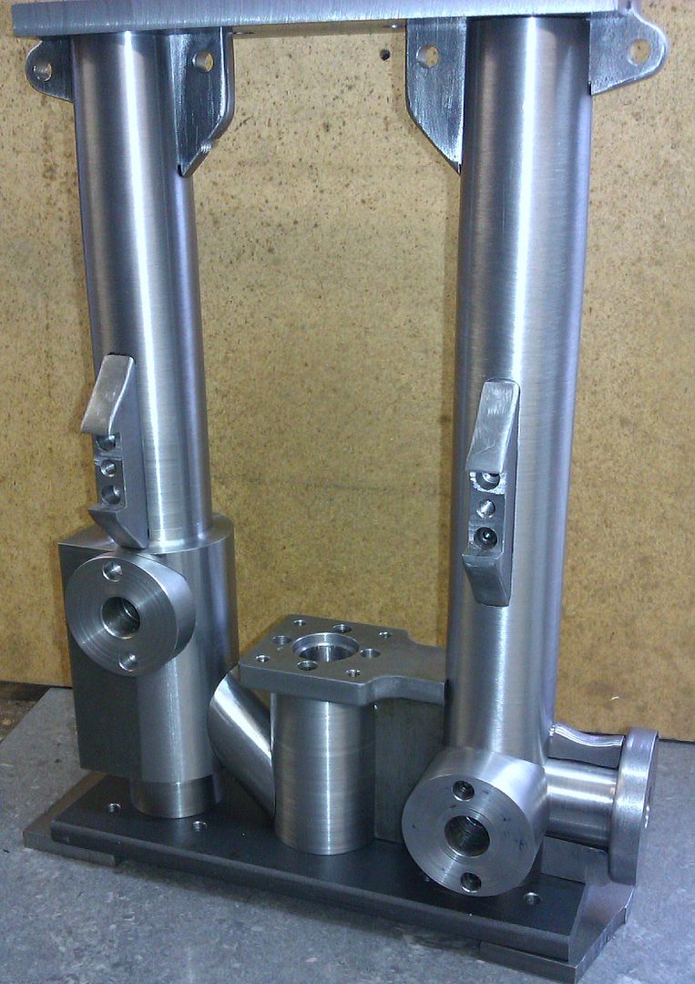
Just the base plate to shape and add a recess for a cover plate that will allow access to the bottom of the pump chamber.


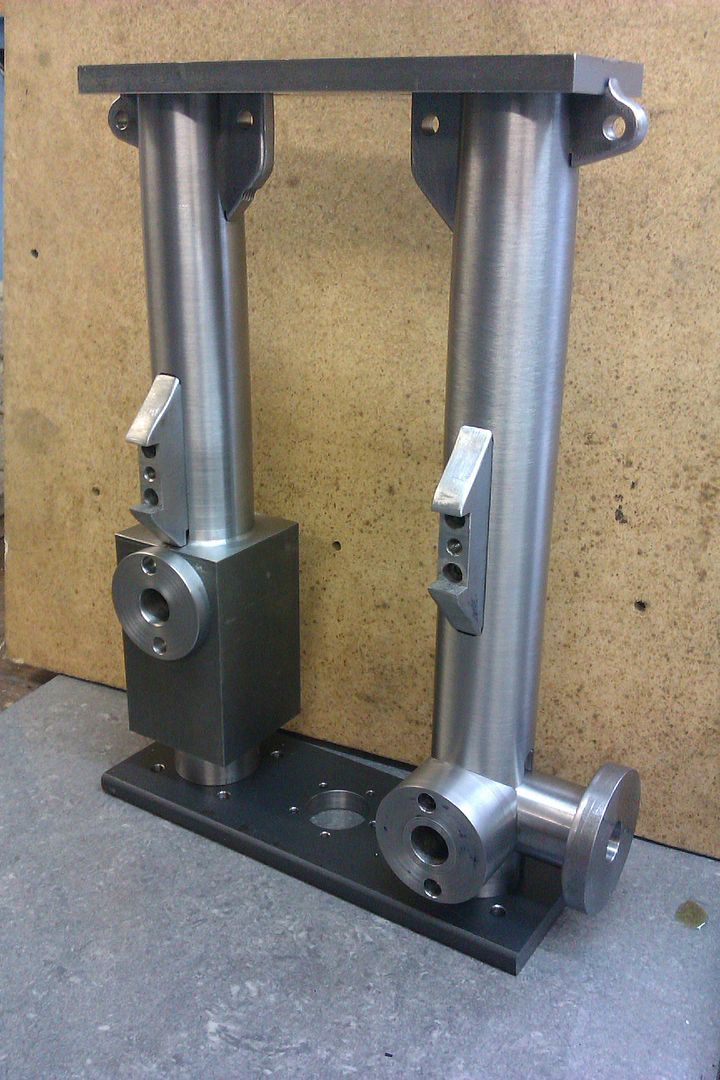
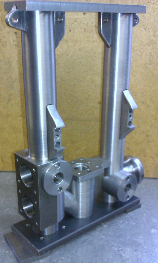
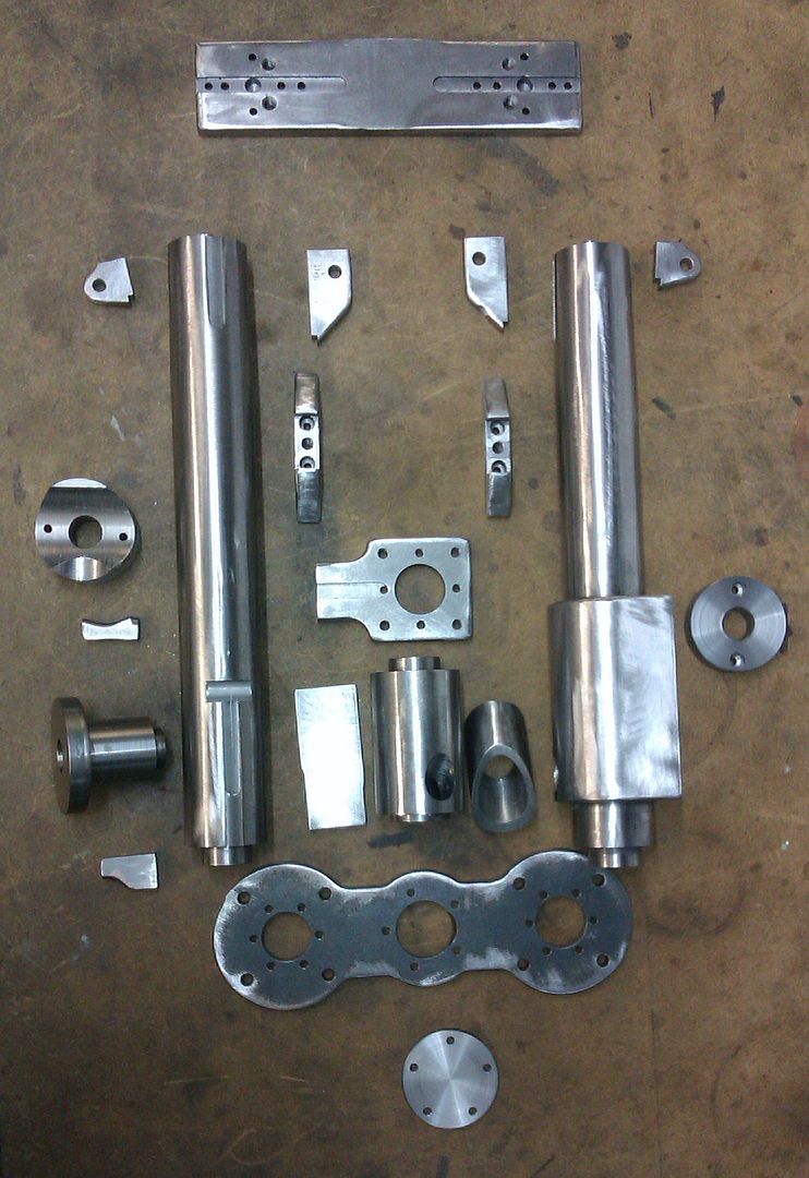
With all the parts made I then went over them all with a flap wheel to soften the surfaces and particularly the external corners so that it will end up looking more like a casting than just a painted "barstock" assembly. It was then assembled with JB Weld and lots of M3 socket screws.


Once set the assembly could be treated like a casting and the faces mentioned earlier machined to finished size and some additional holes drilled and tapped. The DRO does come into its own here, those two flanges both have a 6 hole PCD pattern but it is rotated at 24.3 degrees which would of been a bit of a head ache to work out manually.


Final job was to fill all the internal corners with body filler and then blend everything in ready for paint. I'll cover the link pipe next time.


J


Offline fumopuc

  • Full Member
  • *****
  • Posts: 3254
  • Munich, Germany, EU
Re: Pumped Up Cameron Steam Pump
« Reply #18 on: January 01, 2015, 07:33:17 PM »
WOW, the Bavarians here say it with one word "respect".
« Last Edit: January 01, 2015, 07:57:33 PM by fumopuc »
Kind Regards
Achim

Offline smfr

  • Full Member
  • ****
  • Posts: 1203
  • San Francisco Bay Area, California
Re: Pumped Up Cameron Steam Pump
« Reply #19 on: January 01, 2015, 07:37:31 PM »
Wow, that looks amazing, Jason! You have this fabrication down to an art!

Simon

Offline vcutajar

  • Full Member
  • *****
  • Posts: 2555
  • Marsascala, MALTA
Re: Pumped Up Cameron Steam Pump
« Reply #20 on: January 01, 2015, 07:52:56 PM »
Triple WOW.

Vince

Offline b.lindsey

  • Global Moderator
  • Full Member
  • *****
  • Posts: 13860
  • Dallas, NC, USA
    • Workbench-Miniatures
Re: Pumped Up Cameron Steam Pump
« Reply #21 on: January 01, 2015, 09:00:18 PM »
Amazing stuff Jason!!  I look forward to each new update. I agree with Alan....better than a casting!

Bill

Offline Don1966

  • Full Member
  • *****
  • Posts: 6818
  • Columbia, MS
Re: Pumped Up Cameron Steam Pump
« Reply #22 on: January 01, 2015, 09:03:08 PM »
Awesome Jason and you have me glued to till the next post.  :ThumbsUp:

 :popcornsmall:
Don

Offline Dave Otto

  • Full Member
  • *****
  • Posts: 4707
  • Boise, Idaho USA
    • Photo Bucket
Re: Pumped Up Cameron Steam Pump
« Reply #23 on: January 01, 2015, 10:13:46 PM »
Impressive piece of work Jason!

Dave

Offline Steamer5

  • Global Moderator
  • Full Member
  • *****
  • Posts: 1272
  • The "Naki" New Zealand
Re: Pumped Up Cameron Steam Pump
« Reply #24 on: January 02, 2015, 01:42:22 AM »
Jason,
 That is an impressive bit of work! Most insperational! Can I ask how long it took to figure out how you were going to attack the build, then how long it took to machine?

Cheers Kerrin
Get excited and make something!

Offline FLG

  • Full Member
  • ****
  • Posts: 90
Re: Pumped Up Cameron Steam Pump
« Reply #25 on: January 02, 2015, 05:02:19 AM »
What an incredible work have you done here! I'm looking forward to see this project finished, you got a very original and effective way to assemble "bar stock castings", congratulations!

Saludos

Offline Roger B

  • Global Moderator
  • Full Member
  • *****
  • Posts: 6164
  • Switzerland
Re: Pumped Up Cameron Steam Pump
« Reply #26 on: January 02, 2015, 07:56:57 AM »
Magnificent fabrication  :praise2:  :praise2:  What, if anything, do you use to degrease the fabrication before you apply the body filler?
Best regards

Roger

Offline Jasonb

  • Full Member
  • *****
  • Posts: 9490
  • Surrey, UK
Re: Pumped Up Cameron Steam Pump
« Reply #27 on: January 02, 2015, 03:29:19 PM »
Thanks again for all the comments.

Kerrin, I suppose the figuring out starts once I look at the drawings/photo/etching of a possible subject, once I decide it is doable then as I draw it up for myself I am always thinking how the part will be made - no point in drawing something you can't do. So by the time I have got my plans done I know fairly well how each piece will be tackled though some of the minor details are done as I go along or altered if I come across some extra images or detail of the originals.

As for how long, I looked at the dates on the photos, I took the one of the pile of metal for the columns 4 weeks before the finished one. So thats usually a couple of evenings a week and some time at the weekends though unlike Jo I'm not in the workshop dawn till dusk. I first cut metal on this model at the beginning of September and as of today have two small items left to make so about a 4month build But I have been getting another engine to run and working on another during that time too ;)

Roger, I usually wipe down with fibreglass brush cleaner which is basically a reclaimed acetone. You should be able to get it from any fibreglass suppliers

J

Online Jo

  • Administrator
  • Full Member
  • *****
  • Posts: 15305
  • Hampshire, england.
Re: Pumped Up Cameron Steam Pump
« Reply #28 on: January 02, 2015, 04:40:44 PM »
So thats usually a couple of evenings a week and some time at the weekends though unlike Jo I'm not in the workshop dawn till dusk.

Even I have to work for a living  :shrug:. So only when I am on my holidays do I get the possibilities of longer workshop hours, when I am not maintaining my half an acre of grounds or doing the never ending domestic duties :Doh:

I know of the location of a set of castings for one of these  :naughty:

Jo
Enjoyment is more important than achievement.

Offline Roger B

  • Global Moderator
  • Full Member
  • *****
  • Posts: 6164
  • Switzerland
Re: Pumped Up Cameron Steam Pump
« Reply #29 on: January 02, 2015, 07:57:06 PM »
Thank you Jason, I will have to see what I can get here, the Swiss can be a bit funny about chemicals. The base of my horizontal engine will need some filler  ::)
Best regards

Roger


SimplePortal 2.3.5 © 2008-2012, SimplePortal